P—P70, P72, and P170 Controls for Dual Pressure Applications Product/Technical Bulletin 3
D
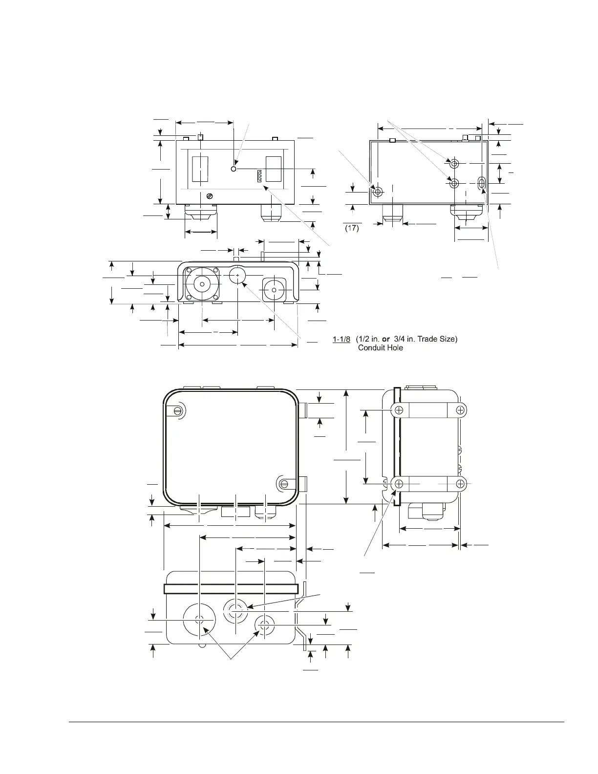
imensions
2-1/16
Diameter
Mounting Hole
Two Mounting Holes
10-32 UNF-28 Thread
5
(127)
5/16
(8)
5/16
(9)
1
(25)
1-1/8
(29)
1-15/16
(48)
15/16
(95)
11/16
3-1/4
(83)
13/16
(20)
1-3/4
(44)
1-11/16
(43)
15/16
(95)
5-11/16
(144)
3-3/16
(80)
3
(76)
1-5/16
(33)
1 5/16
(33)
15/16
(24)
1/16
(2)
3/16
(4)
(53)
11/16
(18)
3/16
(5)
5/16
(8)
1-11/16
(43)
5/16
(15)
2-7/8
(73)
Reset Button for Controls
with both High and Low
Side Reset
Reset Lever for Controls
with High Side Only Manual Reset
(Except P70S and P170S Models)
3/16
(5)
3/8
(10)
X
3/16
(5)
Diameter
Mounting Hole
7/8
(22) (28)
or
Figure 2: Dimensions for P70, P72, and P170 Dual Pressure Controls with NEMA 1 Enclosure, in. (mm)
1-1/4
(32)
3/8
(10)
2-3/4
(69)
4-7/16
(112)
5-13/16
(148)
1-3/4
(44)
1-1/8
(29)
7/16
(10)
2-3/4
(70)
3-3/8
(86)
1/16
5/16
(2)
3-1/8
(79)
4-13/16
(122)
5/8
(16)
5/8
(16)
1-3/8
(35)
Element as Specified
Four Mounting Holes
(8)
Diameter
3/4-NPSM Threaded Rigid
Conduit Connector
Figure 3: Dimensions for P70, P72, and P170 Dual Pressure Control with NEMA 3R Enclosure, in. (mm)
Note: These dimensions are nominal and are subject to accepted manufacturing tolerances and application variables.

 Loading...