P—P70, P72, and P170 Controls for Dual Pressure Applications Product/Technical Bulletin 7
IMPORTANT: Use the pressure control settings
recommended by the
manufacturer of the controlled
equipment. Do not exceed the
pressure ratings of the controlled
equipment or any of its
components when checking
pressure control operation or
operating the controlled
equipment.
IMPORTANT: After installing and adjusting
pressure control, and before
leaving installation, cycle the
controlled equipment several
times (at least three) at normal
operating conditions. Use reliable
pressure gauges to verify proper
control settings and equipment
operation.
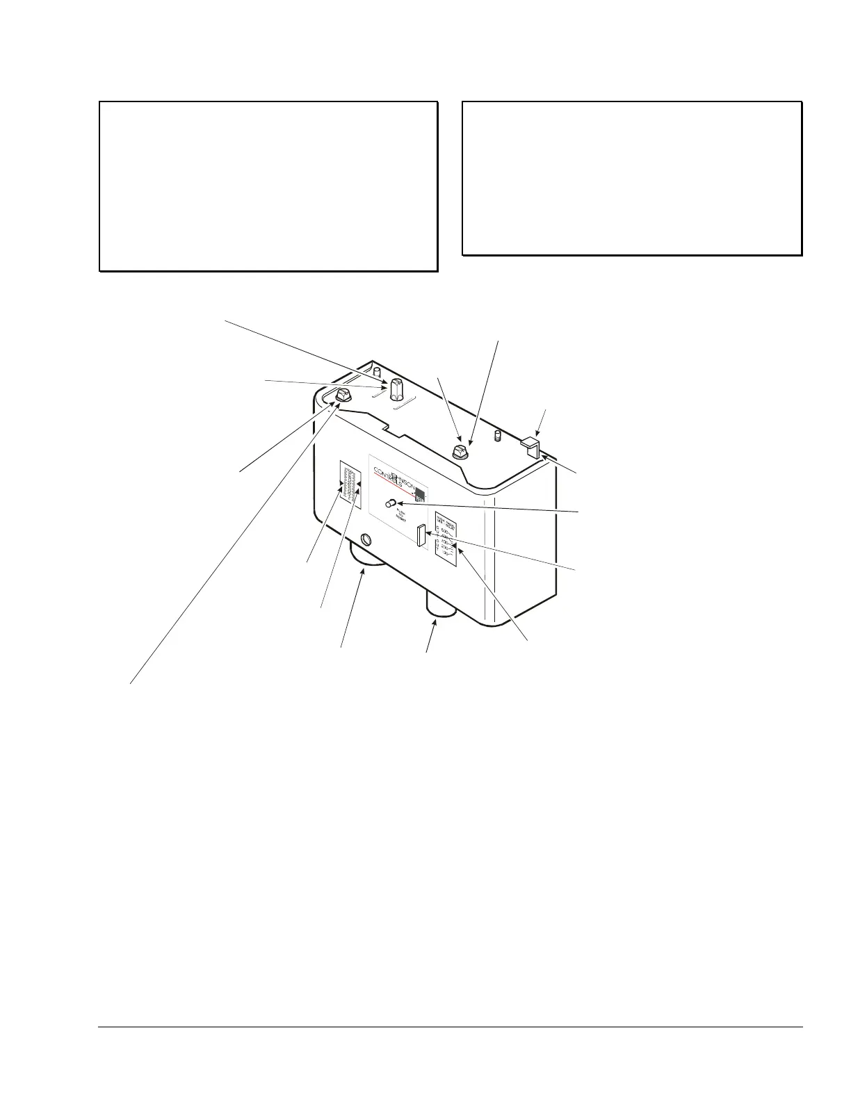
Step 1. Set low side CUT IN by adjusting low side range screw.
Turn screw clockwise to raise the CUT IN setpoint.
Turn screw clockwise to lower the CUT IN setpoint
All-Range Controls:
MICRO-SET Controls:
.
Step 2. Adjust the differential screw.
Turning the differential screw changes the
CUT OUT setpoint. Turn screw clockwise to raise CUT OUT setpoint.
Turning the differential screw changes the
differential setting. Turn screw clockwise to increase differential setting.
All-Range Controls:
MICRO-SET Controls:
Step 3. Set high side CUT OUT setpoint by
adjusting high side range screw.
Turn screw clockwise to raise the
CUT OUT setpoint. (High side
differential setting is fixed.)
Step 4. Set reset operation (on P70S
and P170S models only) for
high side automatic reset or
manual reset lockout.
(See Figure 11.)
Low Side
Range Screw
Differential Screw
(Low Side Only)
Low Side CUT OUT
or DIFFERENTIAL
Pointer
Low Side CUT IN
Pointer
High Side
Range Screw
High Side CUT OUT
Pointer
Low Side
Bellows
High Side
Bellows
Manual Reset Button for P70M, P170M,
P72M, P70Q, and P170Q Models
High Side Manual Reset Only)
(
Manual Reset Button for P70N, P170N,
P72N, P70R, and P170R Models
(Combination Low Side and High Side
Manual Reset)
Manual Reset Button for P70S and
P170S Models (Convertible High Side
Manual or Automatic Reset)
or
or
Figure 10: Adjusting the Dual Pressure Controls
Manual Reset Operation
Pressure controls with the Manual Reset option lock
out when they reach the CUT OUT pressure setpoint
and must be manually reset by the user to restart the
controlled equipment. The manual reset mechanism is
“trip-free” and cannot be overridden by blocking or
tying the reset button down.
On equipment with locked out controls, first determine
and remedy the cause of the lockout before
proceeding.
When lockout is caused by the control’s low side
CUT OUT, allow the sensed pressure to raise to the
CUT IN setpoint.
When lockout is caused by the control’s high side
CUT OUT, allow the sensed pressure to drop at least
70 psig below the CUT OUT setpoint.
After the sensed pressure has reached the desired
pressure (as described above), press and release the
Reset button on the front of the control to restore
operation of the controlled equipment.

 Loading...