P—P70, P72, and P170 Controls for Dual Pressure Applications Product/Technical Bulletin 5
Avoid Contact Between the Capillary Tube and
Sharp or Abrasive Objects
Vibration of sharp or abrasive objects in contact with
capillary tubes can result in leaks.
Do Not Overtighten Flare Nuts on Pressure
Connection Line Fittings
Overtightening flare connections may damage the
threads on the flare nuts or flare connectors, and may
result in leaks. Do not exceed 9 ft-lb (12 N-m) of
torque when tightening brass flare connections.
Avoid Severe Pressure Pulsation at High Side
Pressure Connections
Install pressure connection lines to pressure tap points
away from the compressor, to minimize the affects of
pressure pulsation from reciprocating compressors.
IMPORTANT: After installing control, evacuate
control and pressure connection
lines in accordance with
applicable EPA and other
regulations, to remove air,
moisture, and other
contaminants.
W
iring
P70, P72, and P170 controls for dual pressure
applications are available with several switch options
and electrical ratings. Check the label inside the
control cover for model number, switch action, and
electrical rating. (See Table 1 for switch action and
models.) Check the wiring terminal designations on the
control switch block and refer to the following
guidelines and applicable wiring diagrams, when
wiring the control.
!
WARNING: Risk of Electrical Shock.
Disconnect power supply before
making electrical connections to
avoid possible electrical shock or
equipment damage. On multiple
circuit units, more than
one disconnect may be required
to completely de-energize
equipment.
IMPORTANT: Use terminal screws furnished in
the switch block. Using other
terminal screws will void the
warranty and may damage the
switch.
IMPORTANT: Make all wiring connections in
accordance with the National
Electrical Code and all local
regulations. Use copper
conductors only. Do not exceed
the control’s electrical rating.
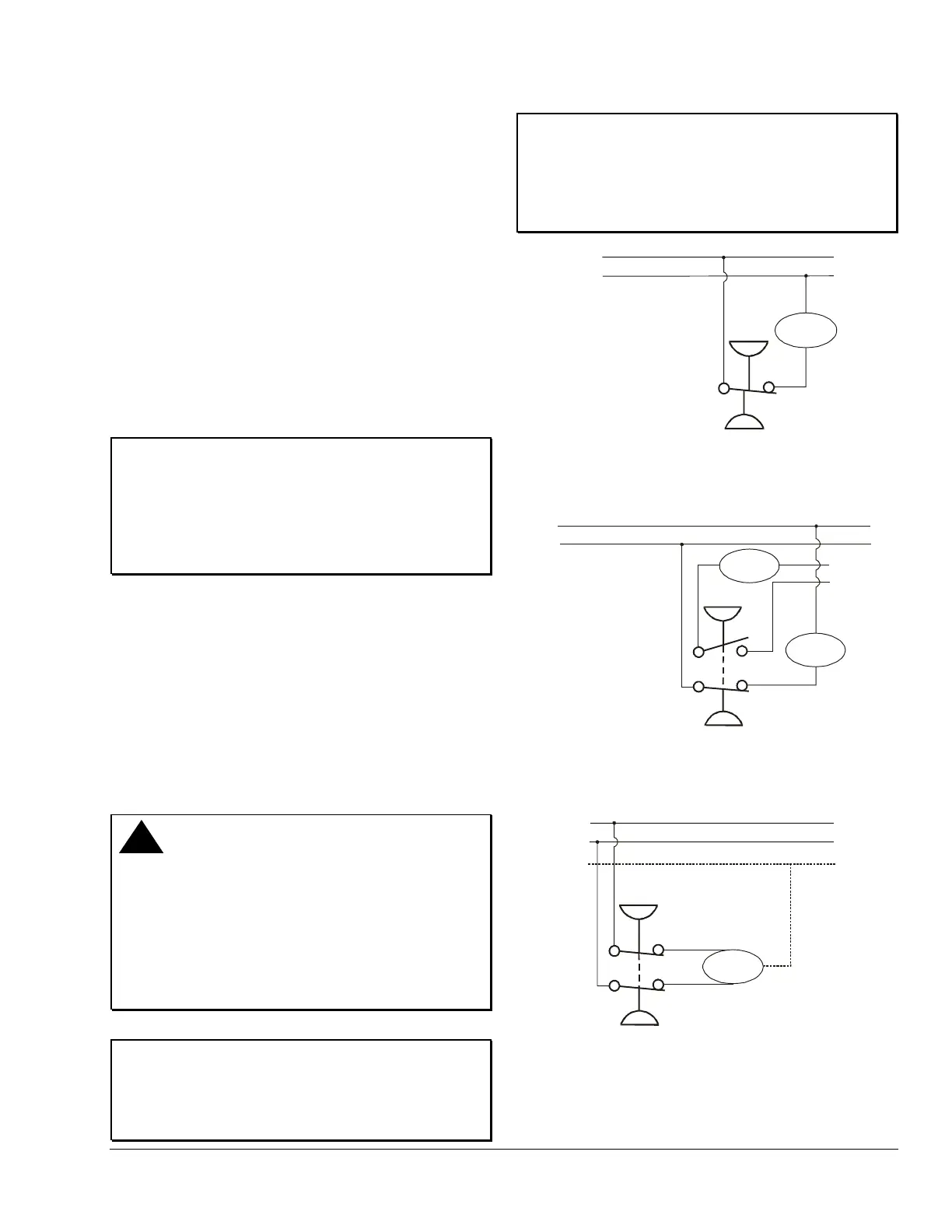
M1
L1
L2
Load
Low
High
Low side opens Line
to M1 on pressure drop.
High side opens Line
to M1 on pressure rise.
Line
Figure 5: Typical Wiring for SPST Switch
(P70L, M, and N, and P170L, M, and N Models)
L1
L2
Low
High
Load
Line
Line
M1
M2
larm
Circuit
Power
Alarm
Low side opens Main
circuit (Line to M2),
and closes auxiliary
circuit (Line to M1)
on pressure drop.
High side opens Main
circuit (Line to M2),
and closes auxiliary
circuit (Line to M1)
on pressure rise.
Figure 6: Typical Wiring for 4-wire, 2-circuit Switch
(P70P, Q and R Models)
L1
L2
Low
High
Load
Line
Line
M1
M2
Low side opens Line to M1 and
Line to M2 on pressure drop.
High side opens
Line to M1 and
Line to M2 on
pressure rise.
L3*
*(L3 is third supply line in 3-phase applications.)
Figure 7: Typical Wiring for DPST Switch
(P72L, M, and N Models)

 Loading...