2
System 350
A350A/B Electronic Temperature Control Product/Technical Bulletin
A
pplication
The A350A/B Temperature Control can be used as
a standalone device or in conjunction with other
System 350 plug-together modules to control single or
multiple-stage HVAC or refrigeration equipment.
Typical applications include:
•
frozen/refrigerated food cases
•
cooling tower control
•
beverage/milk coolers
•
chiller staging
•
space temperature control
A typical System 350 Temperature Control
arrangement includes the following:
•
A350A/B Temperature Control
•
S350 Stage Modules
•
D350 Digital Temperature Sensor/Setpoint Display
Module
•
Y350R Power Module (or Class 2
24 VAC transformer)
•
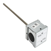
A99B Series Temperature Sensor
O
peration
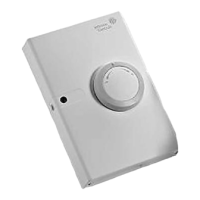
The A350A/B Temperature Control operates on
24 VAC and provides an SPDT relay output. A front
panel LED lights to indicate when the relay is
energized. Adjustable features include:
•
setpoint
•
differential
•
heating/cooling mode
IMPORTANT: All System 350 Controls are
designed for use
only
as
operating controls. Where an
operating control failure would
result in personal injury and/or
loss of property, it is the
responsibility of the installer to add
devices (safety, limit controls) that
protect against, or systems
(alarm, supervisory systems) that
warn of, control failure.
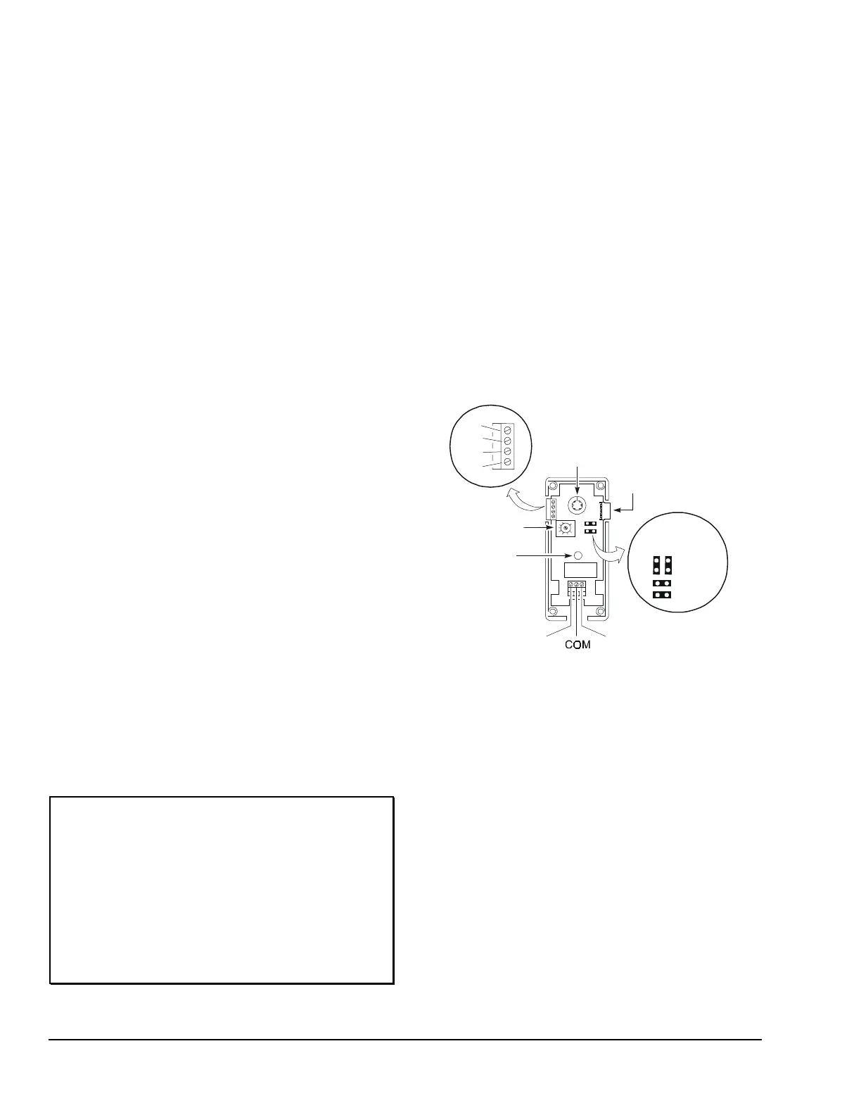
Setpoint Adjustment
Setpoint is defined as the temperature at which the
A350A/B’s relay de-energizes. Use the Setpoint Dial on
the front of the A350A/B to adjust setpoint. See
Figure 2.
Differential Adjustment
Differential is defined as the change in sensor
temperature between energization and de-energization
of the relay. Adjustment of the A350A/B differential is
made using the potentiometer marked DIFF. See
Figure 2 for its location. Refer to Table 5 for
adjustment ranges.
Relay
Module
Connector
Relay
LED Indicator
Setpoint
Dial
DIFF
(Differential
Potentiometer)
Jumper Block
Position
Heating
Cooling
24V
COM
VDC
SEN
NC
NO
Figure 2: A350A/B Board Layout and
Terminal Locations
Heating/Cooling Mode Adjustment
With
Heating mode
selected, the differential is below
setpoint. The relay and LED indicator will de-energize
as the temperature rises to the setpoint. As the
temperature drops to the setpoint
minus
the differential
setting, the relay will energize and the LED illuminates.
Refer to Figure 6.
With
Cooling mode
selected, the differential is above
setpoint. The relay and LED indicator will de-energize
as the temperature drops to setpoint. As the
temperature rises to the setpoint plus differential
setting, the relay will energize and the LED illuminates.
As shipped from the factory, the heating/cooling
jumper blocks are installed in the horizontal (cooling)
position. See Figure 2.