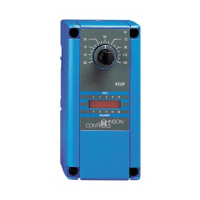
10 System 350 A350P Electronic Proportional Plus Integral Temperature Control Product/Technical Bulletin
3. Check the A350P control for proper operation.
Note: Perform Steps 1 and 2 first.
a. Reconnect the sensor to the control and
re-apply power.
b. Turn the throttling range and the minimum
output to minimum by turning both
potentiometers counterclockwise.
c. Switch off the integration.
d. Select the RA mode.
e. Connect the DVM (+) lead to the A350P
control’s Terminal SN and the (-) lead to
Terminal C.
If the sensor voltage is less than 1.8 VDC on
model A350PS-1C or less than 2.3 VDC on
model A350PS-2C, go to Step 3g.
f. If the voltage is greater than 1.8 VDC on
model A350PS 1C or greater than 2.3 VDC on
model A350PS-2C, adjust the setpoint to
120°F (49°C) on model A350PS-1C or 240°F
(116°C) on model A350PS-2C.
The output Terminal V should be less than
0.1 VDC, and all LEDs in the bar graph display
should be off. If not, replace the A350P.
1. Adjust the minimum output to the
maximum by turning the potentiometer
CW. As the potentiometer is turned CW,
the LEDs in the bar graph should turn on
from left to right until the fifth or sixth bar is
on. If not, replace the A350P control.
2. Adjust the minimum output to zero again,
and select the DA mode.
3. If the right most LED in the bar graph is on
(Terminal V = 10 VDC, Terminal I = 20 mA),
go to Step 3h. If the LED is not on, replace
the A350P.
g. If the sensor voltage is above 1.1 VDC
on A350PS-1C or above 1.6 VDC on
A350PS-2C, adjust the setpoint to match the
actual temperature (T
s
). The output Terminal
V should be less than 0.1 VDC, and all LEDs
in the bar graph should be off.
Note: Some tolerance error is present between the
setpoint scale and the setpoint knob pointer.
Refer to the Adjustments section.
1. Make sure the A350P control is in RA
mode.
2. Increase the setpoint in increments of 2F°
(1C°).
3. As the setpoint is increased, the control’s
Terminal V output voltage should go from
0 to 10 VDC, the Terminal I output current
should go from 0 to 20 mA, and the LEDs
should turn on, one at a time from left to
right.
4. If the LEDs do not turn on and if the
outputs of terminals V and I do not change
as described above, replace the control.
h. Readjust the A350P control to the desired
control settings.
R
epairs and Replacement
Do not make field repairs or perform calibration.
A99B Temperature Sensors and replacement controls
are available through the nearest Johnson Controls
representative. (See Tables 5 and 6 for ordering
information.)
 Loading...