System 350 A350P Electronic Proportional Plus Integral Temperature Control Product/Technical Bulletin 7
Wiring Terminals
Install all wiring to conform to the National Electrical
Code and local regulations. For maximum electrical
rating of control, refer to the label inside the control
cover. Terminals will accept 12 to 26 AWG wire. Use
only copper conductors.
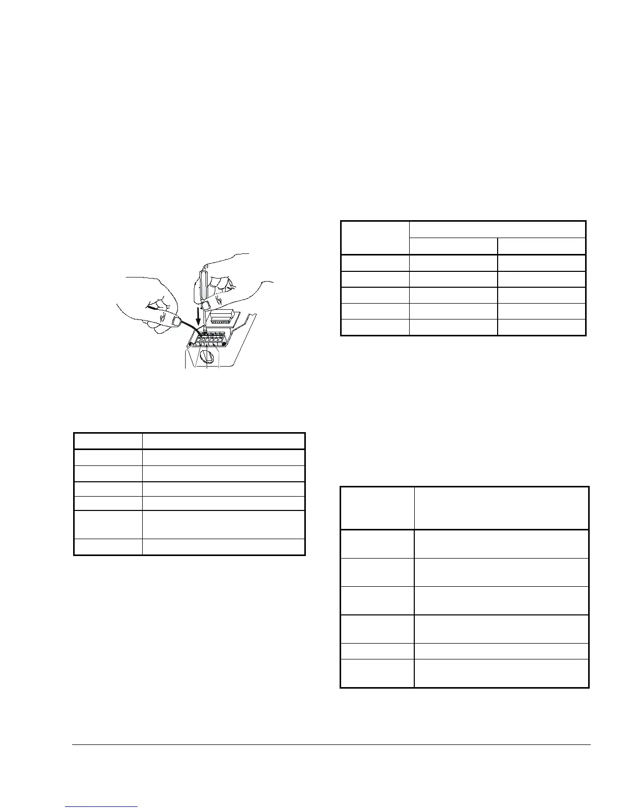
1. Use a 1/8 in. (3 mm) flat-blade screwdriver to push
the clamp arm down.
2. Insert the appropriate wire into the opening.
Refer to Table 2 for terminal designations.
3. Release the clamp arm to secure the wire.
See Figure 7.
Figure 7: Cage Clamp Terminal Block
Table 2: Terminal Designations
V
0 to 10 VDC output
0 to 20 mA output
SN
Temperature sensor input
5 VDC power supply (not used)
Common for power supply,
temperature sensor, and outputs
24V
24 Volts AC
Note: Output signals from the A350P control vary
from 0 to 10 VDC and 0 to 20 mA. (Both
outputs can be used simultaneously.)
Connections can be made to both the V and
I terminals, allowing the control to drive
two outputs from the same RA or DA ramp
simultaneously. This feature can be used to
drive motor actuators of different types in a
single application.
Sensor Connection
Shielded cable is not generally required for sensor
wiring on runs of less than 50 feet. When using
shielded cable, isolate and tape the shield at the
sensor. Connect the shield to Terminal C on the
A350P control.
Refer to Table 3 for the maximum recommended cable
lengths for particular sizes of wire.
Table 3: Maximum Recommended
Sensor Cable Lengths
Feet Meters
14 AWG
800 244
500 152
18 AWG
310 94
20 AWG
200 61
124 38
• Various A99B Series Temperature Sensors and
mounting hardware are available for use with
A350P Series controls.
The sensor must be connected to Terminals SN
and C. (See Figure 2.) The sensors are not
polarity sensitive.
• The sensor must be mounted so that it can
accurately sense the temperature of the controlled
medium.
Table 4: A350P Controls And Sensors
Control Sensor Included
Sensor Lead Length is 9-3/4 in.
(0.25 m)
A350PS-1C
A99BB-25C; Range: -40 to 212°F
A350PS-1CM
A99BB-25C; Range: -40 to 212°F
(-40 to 100°C)
A99BC-25; Range: -40 to 248°F
(-40 to 120°C)
A350PS-2CM
A99BC-25; Range: -40 to 248°F
No Sensor Included
A99BC-25; Range: -40 to 248°F
(-40 to 120°C)
• For more information regarding sensor options
and installation, refer to the A99B Series
Temperature Sensors Product/Technical Bulletin
(LIT-125186).
 Loading...