TEC3000 Series Wireless Proportional Fan Coil and Individual Zone Thermostat Controllers with Dehumidification
Capability Installation Instructions
12
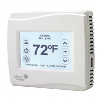
Figure 12: AUX Contact Wiring
Figure 13: Binary Input Wiring
Setup and Adjustments
Overview
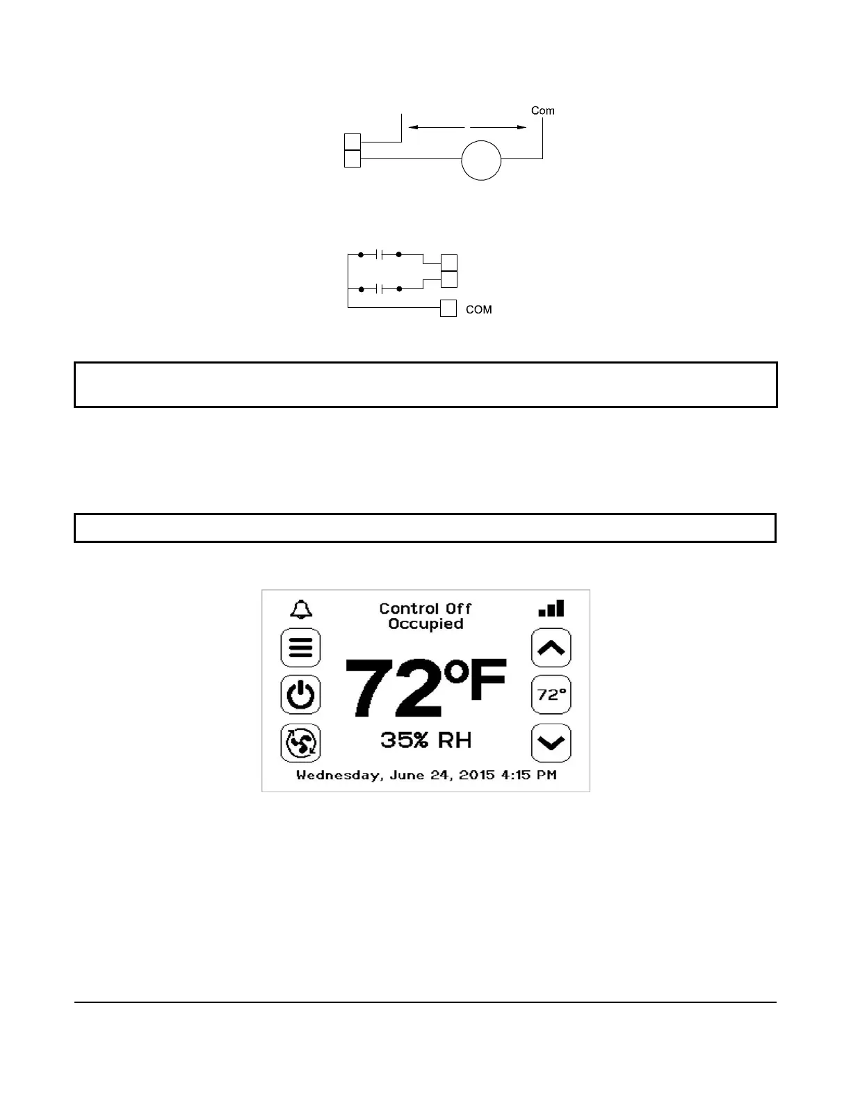
Figure 14 shows the thermostat controller home screen. The home screen can be customized to show or hide
various elements from the occupant. See Table 4 for a listing of the touchscreen icons and Table 10 to identify the
home screen settings under the Display Settings. When screen customization is used in conjunction with a
passcode, the building owner can control which options the occupant can access and adjust.
Figure 14: Thermostat Controller
Home Screen
The humidity level is displayed on the home screen if there is a humidity sensor in the unit, or if the thermostat
controller has a network override written to it.
IMPORTANT: Table 10 provides a full list of TEC3000 menu settings. In the upcoming sections, step-by-step
instructions are included on how to access and adjust the more commonly used menus.
IMPORTANT: If lockout levels are used, some icons are hidden. Table 5 provides details of these levels.
AUX Contact
FIG:Aux Contact Wiring
Load
Hot
19 to 30 VAC
FIG:Binary Input Wiring
BI1
Dry Contact
Dry Contact
BI2
 Loading...