VA-7010 Series Electric On/Off Actuator Product/Technical Bulletin 3
W
iring
!
WARNING:Electrical Shock Hazard.
When servicing, make sure that
the electrical supply to the
actuator is switched off to avoid
personal injury or shock. Do not
attempt to connect or disconnect
wires when the power is on.
!
CAUTION: Equipment Damage Hazard.
Check all wiring connections
before applying power to the
system. Short-circuited or
improperly connected wires will
result in permanent damage to
the equipment.
IMPORTANT: Make all wiring connections in
accordance with the National
Electrical Code and all local
regulations.
To wire the VA-7010 actuator:
1. Run the actuator wires through 3/8 in. Flexible
Metallic Conduit (FMC) or its equivalent as
appropriate.
2. Secure the FMC to the connector provided with
the actuator by tightening the clamp screw using a
1/4 in. flat-blade screwdriver.
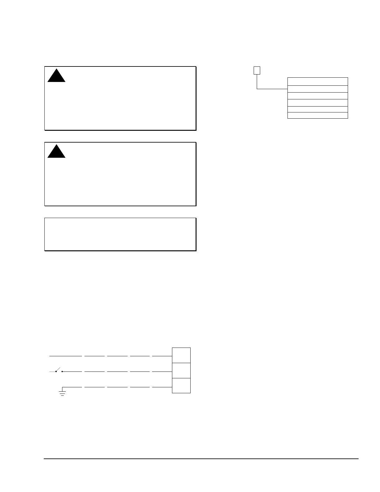
3. Connect the wires as shown in Figure 5 for each
respective model voltage.
White
White
White
Black
Green
White
Yellow
Green
White
Red
Green
White
Blue
Green
Power
Power
Case
Ground
N/A
VA-7010
Power
24
VAC
120
VAC
230
VAC
208
VAC
277
VAC
Figure 5: VA-7010 Wiring Diagram
O
rdering Information
VA-7010-800
1
2
3
6
7
24 VAC
120 VAC
230 VAC
208 VAC
277 VAC
Supply Voltage
Figure 6: Ordering Data for the VA-7010
Actuator Combinations
The VA-7010 Series Electric Valve Actuators are
designed to be used with the VG5000 valve series.
Refer to the VG5000 Series Forged Brass Valves
Product/Technical Bulletin (LIT-977135)
for complete
ordering information.