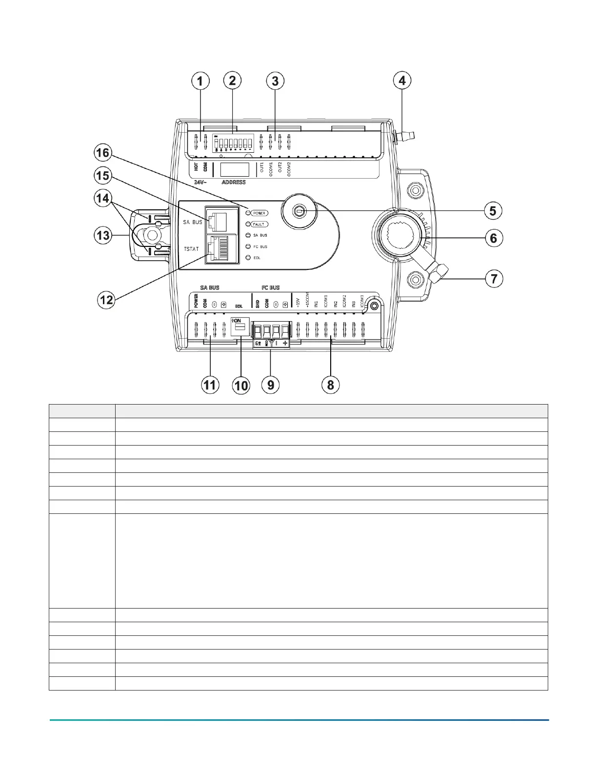
Figure 1: VAV1717 physical features and controller wiring terminations
Callout Description and references
1 24 VAC, Class 2 supply power, see Supply power spade lugs
2 Device address DIP switch block, see Setting the device address
3 Binary outputs, 24 VAC Triacs, see I/O terminal blocks, ratings and requirements
4 Dual port fitting
5 Manual override button, see Mounting the controller
6 Controller coupler, see Mounting the controller
7 Coupler bolt, see Mounting the controller
8 Universal inputs:
• Voltage analog input, 0 VDC to 10 VDC
• Resistive analog input, 0 ohm to 600k ohm, qualified sensors:
• 0 ohm to 2k ohm potentiometer
• RTD: 1k Nickel, 1k Platinum, or A99B Si
• NTC: 10k Type L (10k Johnson Controls Type II is equivalent to Type L) or 2.252K Type II
• Dry contact binary input
See I/O terminal blocks, ratings and requirements.
9 FC bus terminal block: pluggable screw, see FC bus terminal block
10 End-of-line (EOL) switch, see Setting the EOL switch
11 SA bus spade terminals, see SA bus spade lugs
12 TSTAT modular port: RJ-45 8-pin modular jack, see TSTAT port
13 Captive spacer and screw
14 Alignment marks
VAV1717 and VAV1732 VAV Controllers Installation Guide2