Installation
Observe the following guidelines when installing a
VMA1615/1626/1628/1630 controller:
• Transport the controller in the original container
to minimize vibration and shock damage to the
controller.
• Do not drop the controller or subject it to physical
shock.
Parts included
• One VMA1615/1626/1628/1630 controller with
removable SA bus and power terminal blocks
• One installation instructions sheet
• One self-drilling No. 10 x 25 mm (1 in.) screw
• The VMA1628 model includes a 1.25 inch extended
length screw.
Materials and special tools needed
• Several 6 mm (1/4 in.) female spade terminals for
input and output wiring, and crimping tool for
spade mounted terminal blocks
• Small, straight-blade screwdriver for securing
wires in the terminal blocks
• 8 mm (5/16 in.) wrench or 10 mm (3/8 in.) 12-point
socket to tighten the square coupler bolt
• Several shims or washers to mount the VMA
• Power screwdriver, 100 mm (4 in.) extension
socket, punch, drill, and 3.5 mm (9/64 in.) drill bits
to mount the VMA
• Pliers to open and close the damper
• Required length of 3.97 mm (5/32 in.) ID
pneumatic tubing and barbed fittings
Physical features
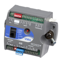
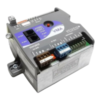
The following figure displays the physical features
of a VMA, and the accompanying table provides a
description of the physical features and a reference
to further information where required.
VMA1615/1626/1628/1630 VAV Controllers Installation Guide2

 Loading...
