Input and Output wiring guidelines
tables
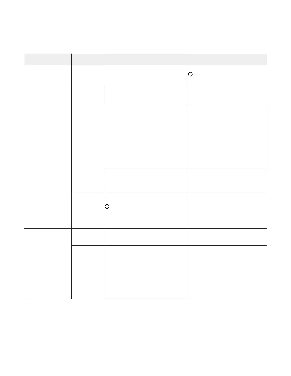
Table 2: I/O terminal blocks, functions, ratings, requirements, and cables
Terminal block label Terminal labels Function, ratings, and requirements
To determine wire size and maximum
cable length
+15 V
15 VDC Power Source for active (3-wire)
input devices connected to the Universal INn
terminals.
Provides 35 mA total current.
Same as (Universal) INn.
Note: Use 3-wire cable for devices
that source power from the +15 V
terminal.
Analog Input - Voltage Mode (0–10 VDC)
10 VDC maximum input voltage
Internal 75k ohm Pulldown
See Guideline A in Table 3.
Analog Input - Resistive Mode (0–600k
ohm)
Internal 12 V, 15k ohm pull up
Qualified Sensors: 0–2k potentiometer,
RTD (1k Nickel [Johnson Controls sensor],
1k Platinum, and A99B Silicon Temperature
Sensor)
Negative Temperature Coefficient (NTC)
Sensor
10K Type L (10K Johnson Controls Type II is
equivalent to Type L) or 2.252K Type II
See Guideline A in Table 3.
INn
Binary Input - Dry Contact Maintained
Mode
1 second minimum pulse width
Internal 12 V, 15k ohm pull up
See Guideline A in Table 3.
UNIVERSAL
(Inputs)
ICOMn
Universal Input Common for all Universal IN
terminals
Note: All Universal ICOMn terminals
are isolated from all other commons
on the -0 models. The -1 model ICOMn
terminals are isolated from FC BUS
COM terminals only.
Same as (Universal) INn.
OUTn
Binary Output - 24 VAC Triac (Internal
Power)
Sources internal 24 VAC power (24~ HOT)
See Guideline C in Table 3.
BINARY
(Outputs)
OCOMn
Binary Output - 24 VAC Triac (Internal
Power)
Connects OCOMn to 24~ COM when
activated.
Internal Power Source:
30 VAC maximum voltage to load
0.5 A maximum output current
1.3 A at 25% duty cycle
40 mA minimum load current
See Guideline C in Table 3.
VMA1615/1626/1628/1630 VAV Controllers Installation Guide 9