9
Original instructions
> English
Pressure and capacity data
(based on water at +20°C/68°F and at
full voltage of the motor)
WD 2.9
Pressure Flow Amp. draw
Bar kPa Psi l/min USGPM 12V 24V
0 0 0 9,4 2,4 2,5 A 1,1 A
0,4 40 5,8 8,8 2,3 3,3 A 1,4 A
0,8 80 11,6 8,1 2,1 4,0 A 1,8 A
1,2 120 17,4 7,3 1,9 4,6 A 2,1 A
1,6 160 23,2 6,7 1,8 5,2 A 2,4 A
2,0 200 29 5,8 1,5 5,8 A 2,7 A
2,4 240 29 4,9 1,3 6,4 A 3,0 A
2,8 280 40,6 4,1 1,1 6,9 A 3,2 A
Fuse required 10 A 5 A
WD 3.5
Pressure Flow Amp. draw
Bar kPa Psi l/min USGPM 12V 24V
0 0 0 12,2 3,2 2,6 A 1,2 A
0,5 50 7,3 11,5 3,0 3,5 A 1,6 A
1,0 100 14,5 11,4 3,0 4,2 A 2,1 A
1,5 150 21,8 11,0 2,9 5,2 A 2,5 A
2,0 200 29,0 10,6 2,8 5,9 A 2,8 A
2,5 250 36,3 10,2 2,7 7,0 A 3,3 A
3,0 300 43,5 9,9 2,6 7,7 A 3,7 A
3,5 350 50,8 9,6 2,5 8,8 A 4,0 A
4,0 400 58,0 9,3 2,5 10,0 A 4,5 A
4,5 450 65,3 9,1 2,4 10,4 A 4,8 A
Fuse required 20 A 10 A
WD 5.2
Pressure Flow Amp. draw
Bar kPa Psi l/min USGPM 12V 24V
0 0 0 18,9 5 3,6 A 1,7 A
0,5 50 7,3 17,8 4,7 5 A 2,4 A
1,0 100 14,5 16,6 4,4 6,6 A 3 A
1,5 150 21,8 15,5 4,1 7,8 A 3,6 A
2,0 200 29 14,5 3,8 9,1 A 4,2 A
2,5 250 36,3 13,4 3,5 10,4 A 4,8 A
3,0 300 43,5 12,4 3,3 11,7 A 5,2 A
3,5 350 50,8 11,4 3 13 A 5,7 A
4,0 400 58 10,6 2,8 13,8 A 6,2 A
4,5 450 65,3 9,7 2,6 14,8 A 6,5 A
5,0 500 72,5 8,7 2,3 15,9 A 7 A
Fuse required 20 A 10 A
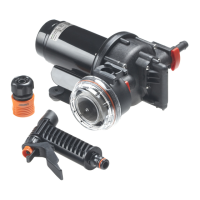
Installation and maintenance
Installation
Locate the pump in a dry location.
If the pump is mounted vertically, the
motor shall face up.
Mark screw positions and drill pilot ho-
les (see drilling template page 48).
Mount the pump using stainless steel
screws and with the accompanying
washers (over the rubber feet); taking
care not to over compress the vibration
dampening rubber feet.
Reinforced, high pressure flexible tubing
is recommended. If rigid pipe is used, a
length (225 mm/9 inches minimum) of
flexible tubing shall be installed between
thepumpandtherigidpipe.Thiswill
address noise and/or damage caused
by vibration transmitted to rigid pipe.
Use stainless steel hose clamps to se-
cure tubing to quick disconnect fittings
and other hose barbs in the system.
A strainer must be installed in line be-
fore the pump intake, to prevent debris
from entering pump and interfering with
proper functioning of valves.
Electrical installation
Thepumpmustbeinstalledaccordingto
ISO 10133 (Small craft – Electrical sys-
tem – Extra low voltage DC installation for
continuouscurrent).Note:Thefusemust
be ignition protected.
The motor is equipped with built in
thermal protection to prevent the mo-
tor from overheating. The protection is
automatically restored when the motor
is cooled.
If the pump is connected with separate
earth lead, this should be yellow/green
and connected to the motor base.
See the wiring table (next page) for
correct installation. Negative wire must
be black.
Choose wire size in accordance with
total wire lenght (see table next page).
Thewireconnectionsmustbesealedwith
a marine sealant.
Note: Before installation with
electrical control systems, check that
equipment to be used is of sufficient
rated capacity to accept amperage draw
of motor. Low voltage will cause motor
to overheat.