901-10113 - 12 - 9/16/2024
3.1 Refrigeration System Diagram
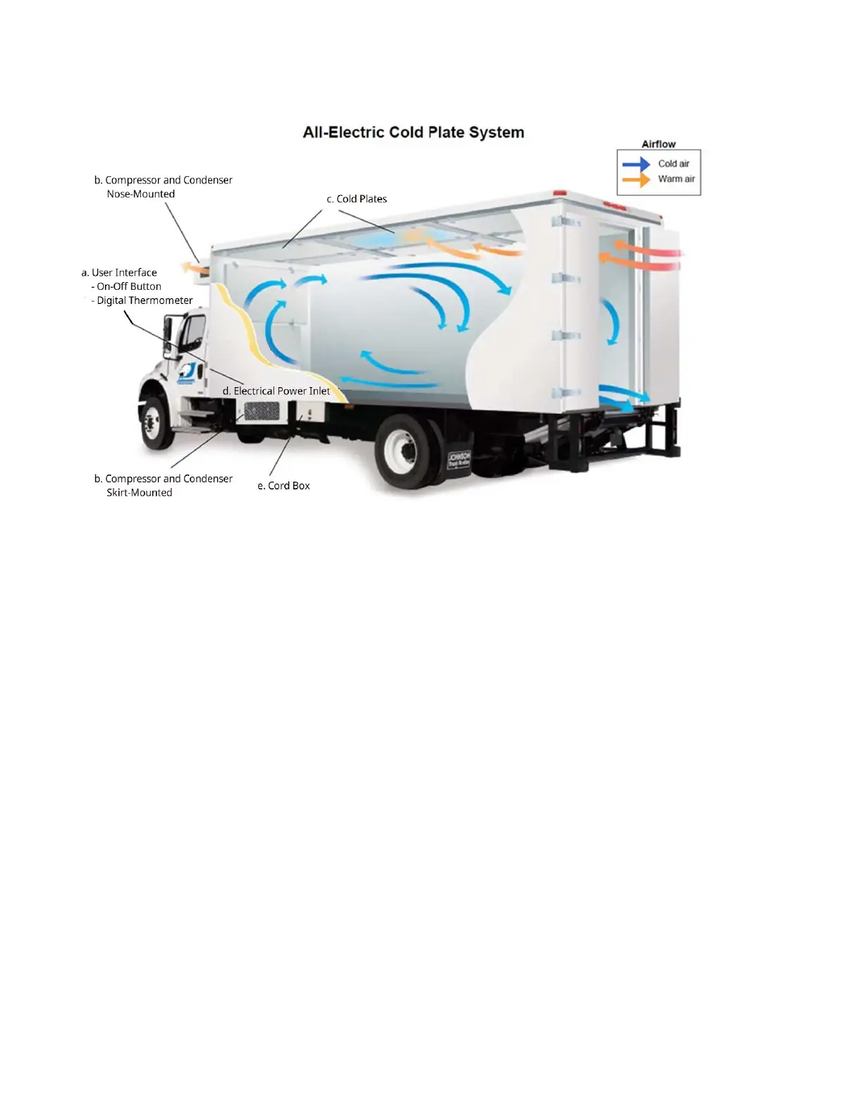
Figure 1: Refrigeration System Diagram
a. User Interface: Located on the driver-side front corner of the body; allows access and display
of refrigeration system information
- A button on the User Interface allows the refrigeration system to be switched on or off;
must be turned OFF before disconnecting the power cord; switch defaults to ON when
system powers on.
- The User Interface includes a Digital Thermometer, displaying the refrigerated
compartment air temperature.
b. Compressor and Condenser: Moves refrigerant through the system and removes heat from
the refrigerant. Powered by electricity to operate when plugged into grid power. Can be nose
mounted or skirt mounted.
c. Cold Plates: Contain a special liquid solution with a freezing point somewhat colder than the
desired temperature of the refrigerated compartment. Refrigerant is used to freeze the
solution solid during plug-in operation. Cold Plates act as large ice packs during delivery routes,
absorbing heat as they thaw, keeping air and cargo chilled in the refrigerated compartment.
d. Electrical power inlet: 250V inlet to plug the refrigeration system into 208-240-volt single-
phase or three-phase AC electrical power; located either on the driver-side front corner or in the
cord box.
e. Cord Box (Optional): for storage of plug-in cord for refrigeration system. Typically includes a
safety interlock switch; the cord box cover must be closed to allow the engine to start or
transmission to shift.