25/30 MODELS
Loosen the five screws attaching the ignition plate
to the retainer plate. Lift the ignition plate from the
powerhead.
1
Remove the four pilot ring screws. Lift the retainer,
ring, thrust washer, and
pilot ring (with washers)
from the powerhead.
1
1
1. Screws
47303
IGNITION
IGNITION PLATE SERVICING
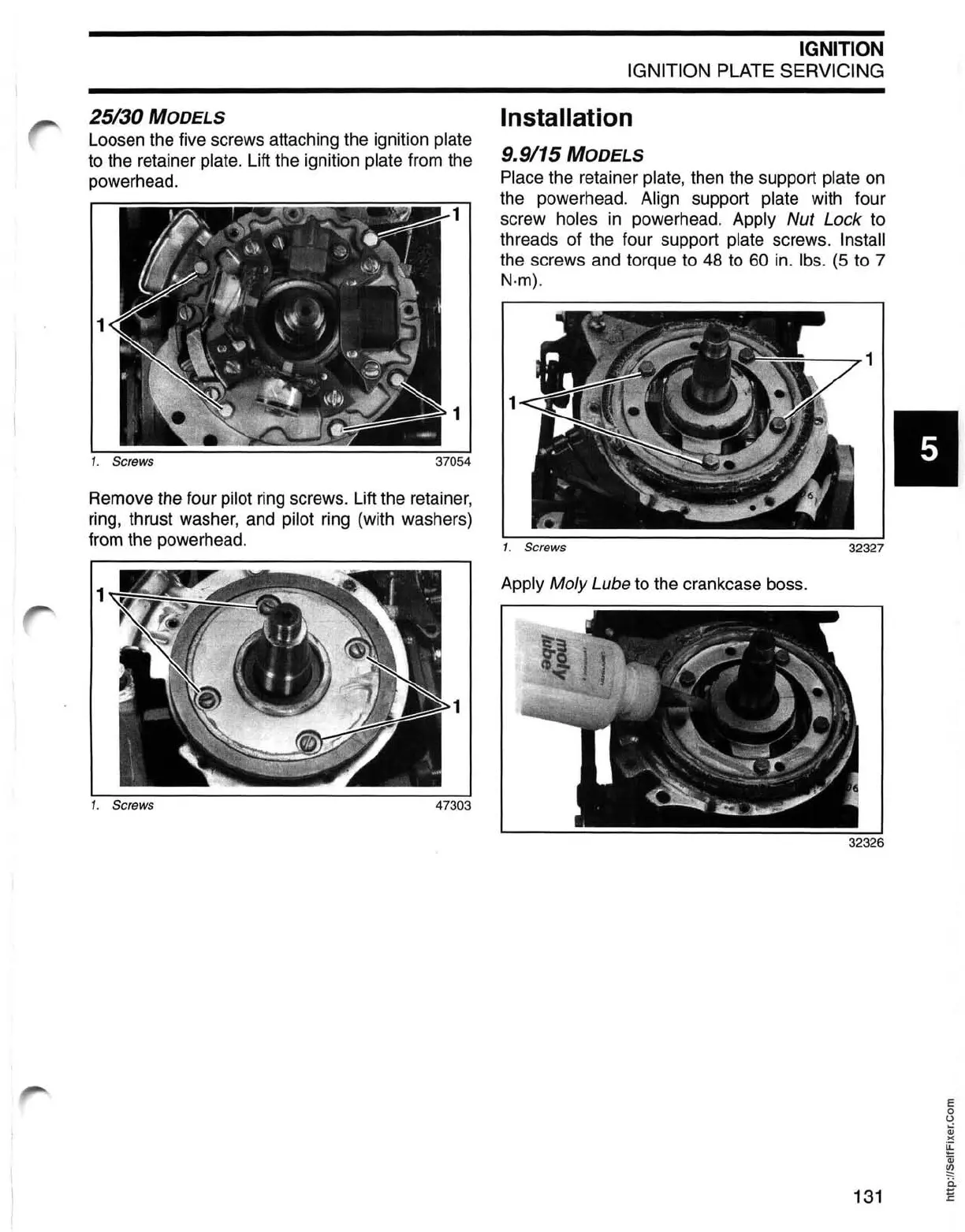
Installation
9.9/15 MODELS
Place the retainer plate, then the support plate
on
the powerhead. Align support plate with four
screw holes
in
powerhead. Apply Nut Lock to
threads of the four support
plate screws. Install
the screws and torque to
48
to
60
in
.
Ibs.
(5
to 7
N·m).
--..,.1
1. Screws
32327
Apply Moly Lube to the crankcase boss.
•
E
o
o
:;j
)(
~
Qj
~
i::i.
131
~