20
Fig. 27
B
A
15. Place the gasket (B) on the edge of the fl ue pipe (A).
16. Insert the fl ue pipe into the rear outlet.
4.6 Performance check
Once the product has been assembled, always check the
control handles. These should move easily and work in a
satisfactory manner.
Fig. 28
Min.
Max.
Max.
Ignition
vent
Air vent
A
B
C
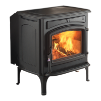
The Jøtul F 130 is equipped with the following operating
options:
Ignition vent (A)
Pushed to the left: Maximum
Pushed to the right: Minimum
Air vent (B)
Pushed to the left:: Minimum
Pushed to the right: Maximum
Stacking height (C) for logs (the holes must not be covered).
ENGLISH


 To Next Page