84
ENGLISH
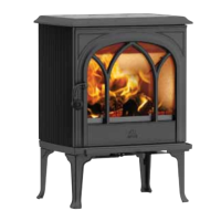
Fig. 9 Installation of cover for outdoor air
(Optional equipment - 50061978)
1. In the case of outdoor air at the bottom of the stove, the
outdoor air cover (A) can be fi tted. This is pushed onto the
pipe from the front.
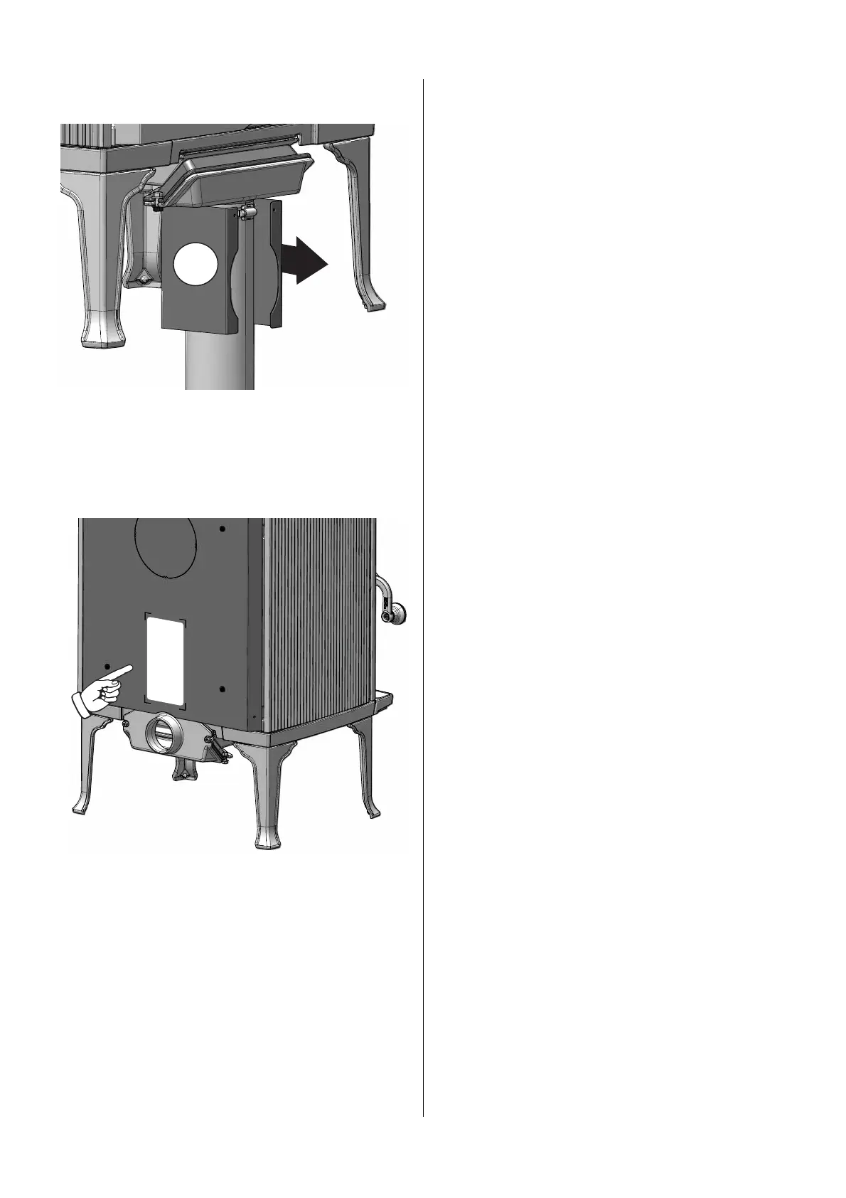
4.4 Location of approval label
Fig. 10 Approval label
1. The approval label is located on the rear heatshield
screen.
4.5 Chimney and fl ue pipe
• The fi replace must only be connected to a chimney and
fl ue pipe approved for solid fuel fi replaces with fl ue gas
temperatures as specifi ed in «2.0 Technical Data».
• For fl ue pipe dimension see “2.0 Technical Data”. NB:
NB:The chimney’s diameter must be at least as big as the
fl ue pipe: Ø150 mm fl ue pipe - 177 cm2.
• Connection to the chimney must be carried out in
accordance with the chimney supplier’s installation
instructions.
• Before a hole is made in the chimney, the product should
be test-mounted in order to correctly mark the position of
the fi replace and the hole in the chimney. See fi g. 1 for
minimum dimensions.
• Use a fl ue pipe bend with a sweep hatch to allow sweeping.
• Flue pipe bends with any change in direction infl uence/
reduce the chimney draught. This eff ect also applies
when horizontal fl ue pipes are used. Please note that it
is extremely important for connections to have a degree
of fl exibility. This is to prevent any movement in the
installation leading to the formation of cracks.
• For recommended chimney draught, see «2.0 Technical
Data».
NB! The minimum recommended chimney length is 4 m from
the fl ue pipe insert. If the draught is too strong, a fl ue pipe
damper can be installed and used to reduce the draugh
If a fl ue damper is fi tted it shall be of a type, which does not
block the fl ue totally. The damper shall be easy to operate and
incorporate an aperture within the blade, which in a continuous
area occupies at least 20 cm2 or 3 % of the cross-sectional
area of the blade if this is greater.
The position of the damper shall be recognizable from the
setting of the device.
If a draught regulator is fi tted the minimum cross sectional
area requirement shall not be applicable but the device shall
be easily accessible for cleaning.
4.6 Performance check
Once the product has been assembled, always check the
control handles. These should move easily and work in a
satisfactory manner.
Fig. 11 Operating options on Jøtul F 200/F 205
B
A
C
1. Handle door (A). Open by lifting the handle up (clockwise)
and pulling out.
2. Air and ignition valve (B). Adjusted in the horizontal
direction (see fi g.12)
3. Air supply hole (C) must not be covered.