6
139473_A 9/11/12
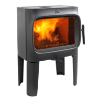
1.2 Flue Collar Orientation
The Flue Collar is oriented in the Top Exit position. To
change orientation to Rear Exit:
1. Twist and remove the perforated cut-out section from
the top edge of the rear shroud.
2. Use a 10 mm open end wrench or socket wrench to
remove the two M6 x 12 bolts that attach the flue collar
to the stove. Orient the flue collar to the rear and use the
same bolts to re-attach it to the stove.
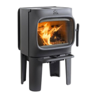
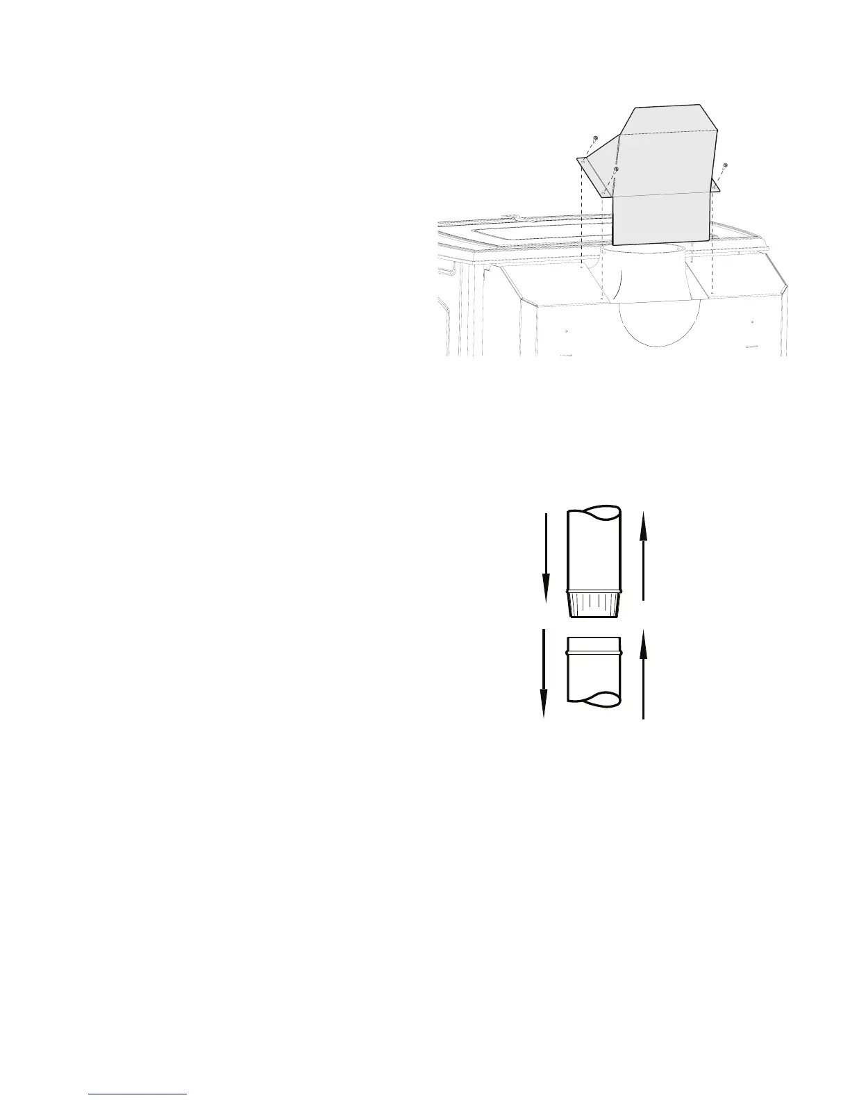
1.3 Flue Collar Heat Shield
Not applicable for rear exit configuration.
1. Fold the heat shield on the perforations to conform to
the shape as illustrated in fig.2.
2. Secure it to the rear stove shroud using the four #8 x 12
sheet metal screws from the hardware bag.
1.4 Chimney Connector
Use 6” single wall or listed 6” double-wall stovepipe to
connect the stove to the chimney. Single wall stovepipe
must be black steel or stainless steel and have a minimum
thickness of 24 gauge. Do not use aluminum or galvanized
steel pipe for chimney connection - these materials are not
suitable for use with solid fuel.
Follow these guidelines:
• Do not use chimney connector as a chimney. It is intend-
ed only as a connection device.
• Each connector section must be oriented with the male
(crimped) end pointing toward the stove. See fig. 3.
• Secure all connector joints with three sheet metal
screws. The connection to the stove flue collar uses the
two M6x 16 mm self-tapping screws provided.
• For the best performance, the chimney connector should
be as short and direct as possible, including no more
than two 90° elbows.
• The maximum vertical run of single wall stovepipe
should not exceed 10 ft. (305 cm).
• Themaximumhorizontalrunshouldnotexceed3ft.
(92 cm) with a 1/4” rise per foot. Under no circumstance
should horizontal pipe be allowed to slant down toward
the chimney.
• No part of the chimney connector may pass through
an attic or roof space, closet or other concealed space, or
through a floor or ceiling. All sections of the chimney con-
nectors must be accessible for cleaning. Where passage
through a wall or partition of combustible construction
is desired, the installation must conform with NFPA 211 or
CAN/CSA-B365, and is also addressed in this manual.
• Donotconnectthisstovetoachimneyflueservingan-
other appliance.
Figure 2. Flue Collar heat shield attachment.
Figure 3. Chimney connector orientation.
 Loading...