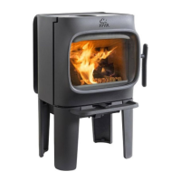
17
ENGLISH
Regulating the pilot flame
The pilot flame should have three flames as shown in fig. 4.
The thermocouple tip should be surrounded by flames (as
shown in the figure). The flames should be stable and the
colour mainly blue. If you detect a deviation from this, turn
off the pilot flame and call for service.
Annual service
Annual service of the stove includes the following check
points.
• Lighting the pilot flame
• Cleaning the glass.
• The gasket around the glass must be inspected annually
for wear and replaced if necessary.
• Check the gas pressure if other gas equipment is
connected to the gas supply.
• Look for signs of corrosion on the firebox and the vent
system.
• Look for obstructions in the vent system (such as bird’s
nests, or branches from bushes and trees).
• Test the operation of the flue system with a smoke
test.
Electrical connections
Fig. 5 illustrates how the product’s wires are connected.
The table below gives a description of the position numbers
in the diagram. Note that if the product is to be operated
by a remote control, the motor (G) must be connected to
the valve (F). The batterybox (H) must be connected to the
motor, using a wire provided, and fastened back on the
heatshield. Contact your dealer for delivery and fitting of
this equipment if required.
Description of parts for the schematic diagram (fig.5)
A Thermocouple
B Snapstat
C El-wire to the snapstat
D El-interupter
E Thermostat
F Valve
G El-motor (Option)
H Battery Box (Option)
I Remote Control (Option)
Operating instructions
Lighting
Note! Odours when using the stove:
When used for the first time, the fireplace may emit an
irritating gas that may smell a little. The gas is not toxic,
but the room should be thoroughly aired out for a few
hours.
During first-time use, it may take a little while before the
gas tube is cleared of air, but subsequently the appliance
should function as described in the lighting instruction.
The appliance operates with the aid of a pilot flame, which
is lit manually according to the lighting instructions.
Prior to lighting: Check the area around the appliance for
possible gas leaks/odors. Especially check near the floor,
since LPG is heavier than air and would gather close to the
floor in the event of a leakage. (Note: Natural gas is lighter
than air and will gather under the ceiling). If you detect an
odour of gas, see warning under: Safety precautions.
Only use your hands to operate the control knobs; do not
use tools. If you are unable to turn or push in the control
knob, do not use force. Call for service.
Do not use the fireplace if any part of it has been submerged
in water. Call for service to replace the parts that have
been in water.
Lighting instructions
Lighting the pilot flame (fig. 2)
• The control knobs are located on the right side of the
appliance.
• Make sure the gas valve on the pipeline to the appliance
is open. Verify that the control knob (2) for gas volume is
in position (max)
• Turn knob (1), slightly to the left towards the ignition
position, until it stops.
• Press the knob down and keep it there for five seconds.
Then turn to the left to activate the piezo.
• If the pilot does not light, continue turning to the right
and left again to activate, until the pilot flames can be
seen down on the left side of the fire box.
• Keep the knob pressed down for ten seconds after the
pilot is lit.
• When lit, release the knob and turn further to the left
to the “ON” position.
Required gas pressure:
Gas type Right testpoint (A) Left Testpoint (B) Hot Left Testpoint (B) Cold
Inlet pressure Set by adjustment Set by adjustment
High Low High Low
Nat.Gas G 20 20 mbar 14,5 mbar 3,6 mbar 13,6 mbar 3,1 mbar
Nat.Gas G 25 25 mbar 18,0 mbar 3,6 mbar 17,0 mbar 3,1 mbar
LPG G 31 (coals only) 30/37 mbar 17,4 mbar 8,9 mbar 16,3 mbar 8,4 mbar
LPG G30/G31 (logs only) 30/37 mbar 23,0 mbar 8,9 mbar 21,9 mbar 8,4 mbar
 Loading...