Revision 1.3 Joulescope JS220 User’s Guide Page 35 / 51
www.joulescope.com
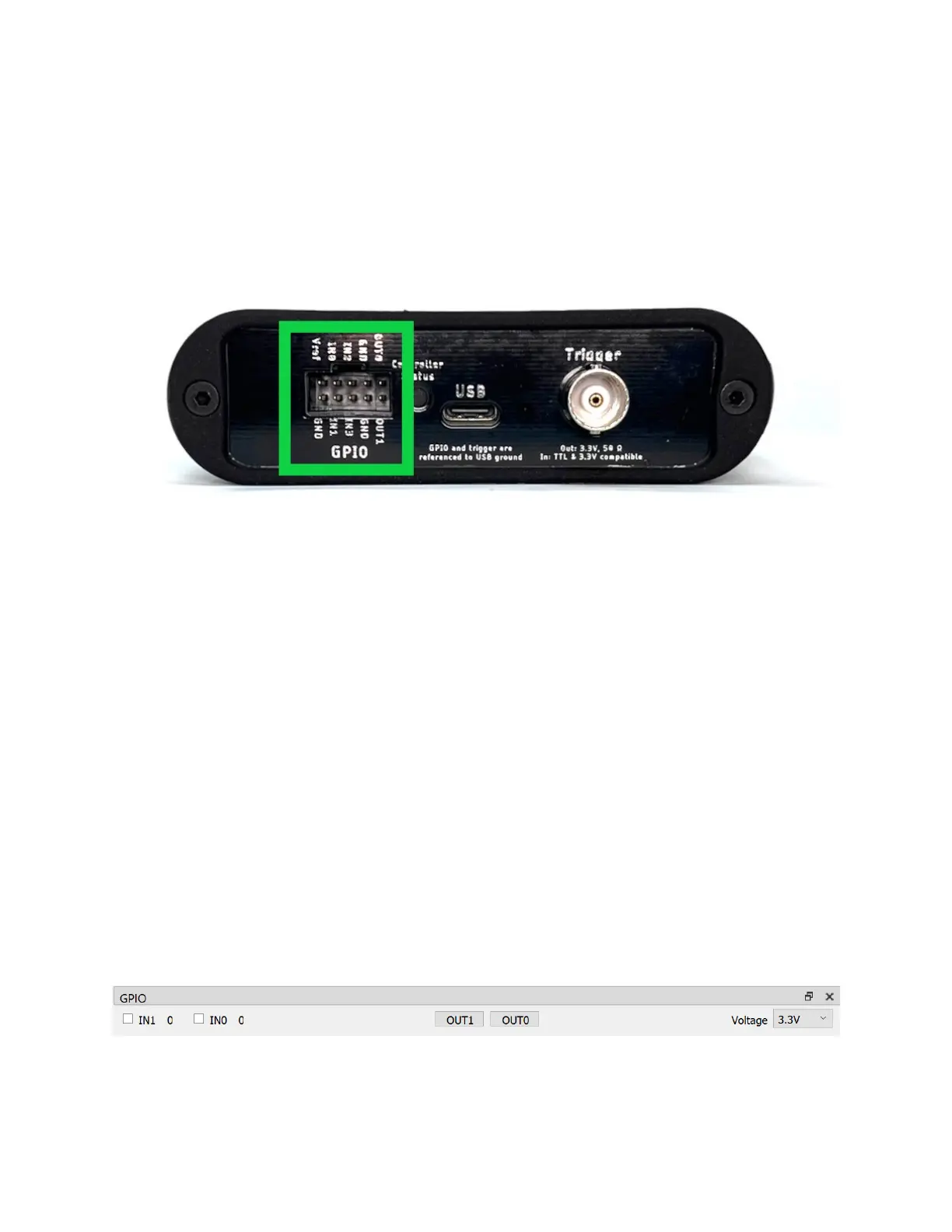
12. GPI & GPO
The Joulescope contains four (4) general-purpose inputs (GPI) and two (2) general-purpose outputs
(GPO) located on the GPIO connector to the left of the host USB connecter. The JS220 includes a GPIO
cable harness that can simplify connecting the GPIO to target devices and breadboards. The BNC Trigger
connector located to the right of the host USB connector can be configured as either an additional
general purpose input or output.
The JS220 software can record the input signals and control the output signals. The input signals allow
the JS220 to monitor other equipment and your device under test. The output signals can be used to
control other equipment or the device under test. The user interface can display inputs time-
synchronized with current, voltage, and power in the oscilloscope view.
One intended application for the GPIs is to allow the target microcontroller firmware to identify areas of
interest. The microcontroller can toggle bits so that you can easily see the energy consumption in the
marked time windows.
The GPIO and Trigger are referenced to USB ground. Many applications using Joulescope will want
isolated GPI/GPO for improved performance. When selecting an isolation solution, consider:
• Electrical isolation
• Self-powered target interface with very low power from target device – leakage currents only
• Variable voltage technology levels with an external reference voltage
• ESD protection
• Overvoltage protection (GPO)
• Short circuit protection (GPO)
• Very high (GΩ) input impedance (GPI)
To control the GPIO, add the GPIO Widget by selecting View → GPIO.
The GPIO includes an external Vref signal. When using the GPIO with your device under test, connect
Vref to the supply voltage on the device under test. Using Vref ensures that the input threshold and
 Loading...