Revision 1.3 Joulescope JS220 User’s Guide Page 9 / 51
www.joulescope.com
Your Joulescope JS220 purchase includes:
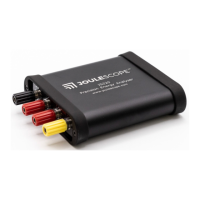
• Joulescope JS220 instrument with factory calibration
• Binding Post Front Panel, already installed
• 5’ USB 2.0 A to C cable
• GPIO cable assembly
• 2 mm Allen wrench, for optionally swapping the front panel
• Quick Start Guide
• Joulescope sticker
• Carry case
You will need to provide:
• A host computer running Microsoft® Windows® 11 or 10, Apple® macOS® 12 or 10.15, or Linux®.
Most computers manufactured within the last five years should work. The computer requires
an available USB 2.0 port, at least 500 MB of hard drive / solid state drive storage space, and 1
GB of available RAM.
• Suitable cable(s) to connect the Joulescope JS220’s binding posts to your system, often the
power source and device under test.
• For computers without USB A ports, a suitable USB cable or USB adapter.
• Optional BNC cable for connecting trigger to other equipment.
You need an internet connection to download the free software.
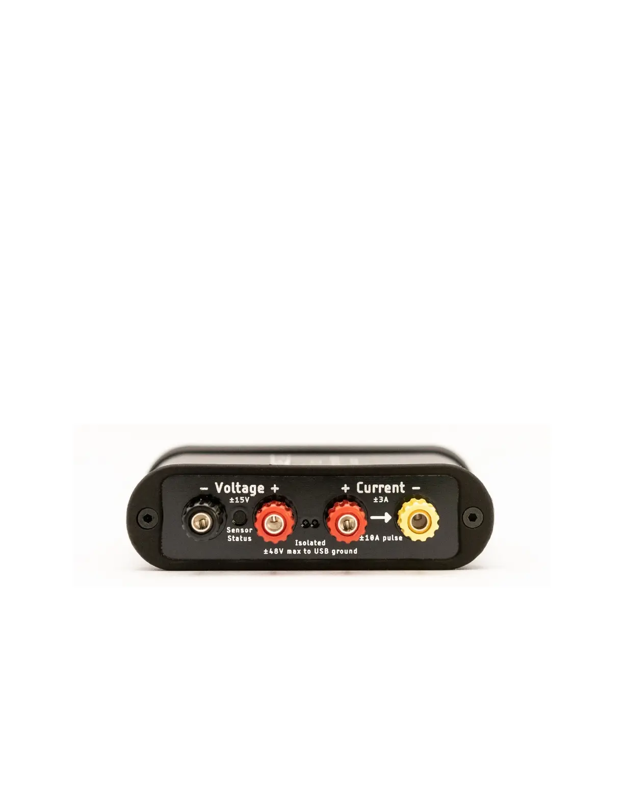
The front side of the JS220 has the connectors that connect to your system:
Your JS220 measures the voltage across the Voltage + and Voltage – binding posts. Your JS220 measures
the current flowing through the Current + to the Current – binding posts. If you have a power source
and target device, connect the positive side through the current binding posts. You can then connect
the voltage signals across either your power source or your target device. For more connection
examples, see Section 9.
The Sensor Status indicator is off when your JS220 is powered off or inactive. Flashing red indicates that
the instrument is ready but the current flow is not yet enabled. Solid green indicates that current
measurement is enabled.
 Loading...