9.03.15
Stitch length scale disk
9.03.15
Stitch length scale disk
,,
。13
,,
。1 3
Requirement
13
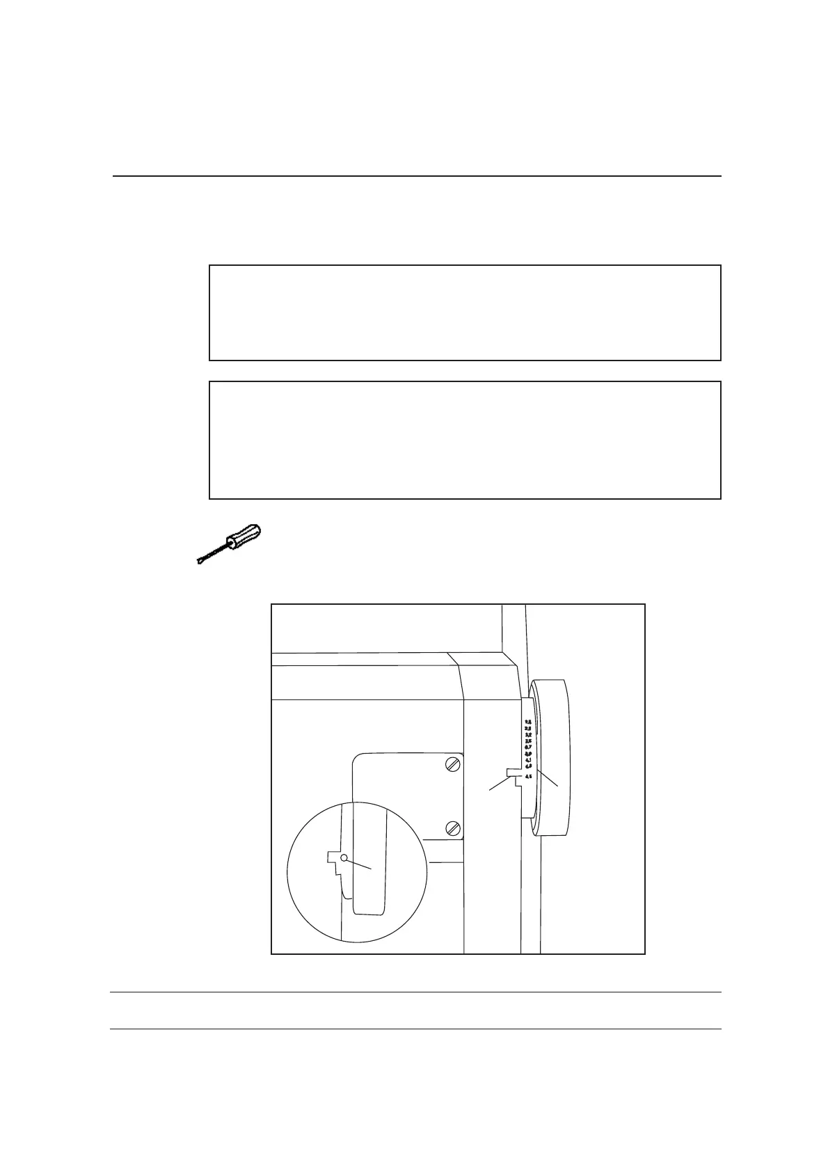
When the stitch length control device is locked in position, and the maxi-
mum stitch length is set, the marking line of the highest number on the
scale disk must be opposite the lower edge of the belt guard recess.
Requirement
1 3
When the stitch length control device is locked in position, and the maxi-
mum stitch length is set, the marking line of the highest number on the
scale disk must be opposite the lower edge of the belt guard recess.
● 。
● ( )。
●
●
12
1 2 Requirement
Set the maximum stitch length.
Turn the scale disk (screw ) according to the .
● 。
●
( )。
●
●
1 2
1 2 Requirement
Set the maximum stitch length.
Turn the scale disk (screw ) according to the .
3
1
2
9-19
Adjustment
Adjustment
9.04.09
Linkage rod
( )9620
(only for the 9620)
9-44
Adjustment
, 。1
Requirement
1When the thread trimmer is in its resting position, the drive levers must be
parallel.
● ( )。
●
1 2
1 2 RequirementAdjust drive levers (screw ) in accordance with the .
9.03.16
Shaft crank to feed wheel drive
, (
)。
3
3 4
9625 9610
Requirement
3 3
4
When the maximum length is set, the linkage rod , or lingkage rods
and on the model 9625 and 9610, must be able to move freely when the
balance wheel is turned.
● 。
●
( )。
●
●
1 2
1 2 Requiremen
Set the maximum stitch length.
Twist or shift the shaft crank ( screw ) according to the t.
9-20
Adjustment
9625
9610
9620
9.04.08
Releasing the tension
Adjustment
9-43
, 。1. 3 0.5 mm
Requirement
3 0.5 mmWhen the magnet is activated, tension discs must be at least
apart.
● 。
● 。
●
●
1 2
1 2
Activate the magnet.
Detach the tension bearing plate and adjust pressure plate .
19 0* 260 6 14
Zj 96 10、9620、9625、9630
08 .0 4.2
 Loading...