9.03.23
Knee lever
,。
,。
。
1.
2.
3. 5 75
Requirement
5 75
1. before the roller presser rises, the knee lever must still have a slight play.
2. when the knee lever is raised as far as possible, the lever for the roller
presser must drop automatically.
3. knee lever bar must be at an angle of approx. to the bedplate.
● ( )。
● ( )。
●
( )。
●
●
●
3 1 2
2 3 4
3 5 6
1 2 Requirement 3
3 4 Requirement 2
5 6 Requirement 3
Adjust screw (nut ) according to .
Adjust screw (nut ) according to .
Set bar (screws ) according to .
9-27
Adjustment
9.04 D
Adjusting the thread trimmer -D
9.04 D
Adjusting the thread trimmer -D
, ,
。
, 。
1.
2.
56
3 0.3 mm
37
, ,
。
, 。
1.
2.
5 6
3 0.3 mm
3 7
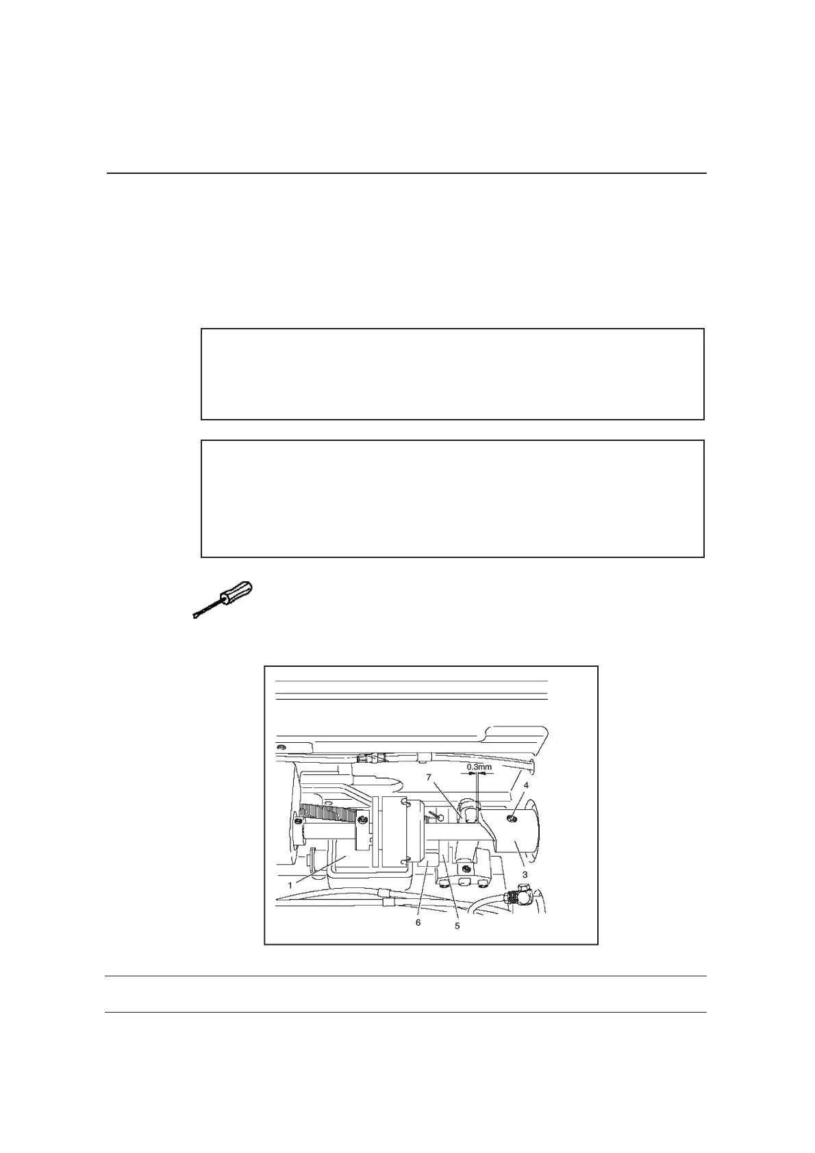
Requirement
5
6 7 0.3 mm
3
3
7
1. when the thread trimmer is in resting positon, lever should be touching
piston and the roller of roller lever should be away from
control cam .
2. when the take-up lever is at top dead centre, control cam should just
have placed roller lever in its resting position.
● ,1 ()。
● ( )。
●
●
61
234
6
1 2 Requirement 1
3 4 Requirement 2
Having made sure that piston is positioned against the left stop,
adjust magnet ( screws) in accordance with .
Adjust control cam (screw ) in accordance with .
● ,1 ()。
● ( )。
●
●
6 1
2 3 4
6
1 2 Requirement 1
3 4 Requirement 2
Having made sure that piston is positioned against the left stop,
adjust magnet ( screws) in accordance with .
Adjust control cam (screw ) in accordance with .
9.04.01 /
Resting position of the roller lever/ radial position of the
control cam
9.04.01 /
Resting position of the roller lever/ radial position of the
control cam
9-36
Adjustment
Adjustment
9.03.24
Needle thread tension release
, 。
,。
1.
2.
3 0.5 mm
Requirement
3
0.5 mm
1. when the presser bar lifter is raised, the tension discs should be
pressed at least apart.
2. When the roller presser is lowered, the tension must be fully effective.
● 、 。
●
1 2
1 2
Reqirement
Align tension mounting plate and pressure plate according to
.
9-28
Adjustment
9.03.30
Re-engage safety coupling
。,
。
。
1
1
1
1
The coupling is set by the manufacturer. When the thread jams, the
coupling disengages in order to avoid damage to the hooks.
A description of how to engage the coupling follows.
● 。
● ,
。
●
●
2 1 1
1 2
1
Remove jammed thread.
Hold coupling with screw and turn the balance wheel, until you feel
coupling snap back into place again.
9-35
Adjustment
19 0* 260 6 16
Zj 96 10、9620、9625、9630
08 .0 4.2
 Loading...