9.03.15
Stitch length scale disk
,,
。1 3
Requirement
1 3
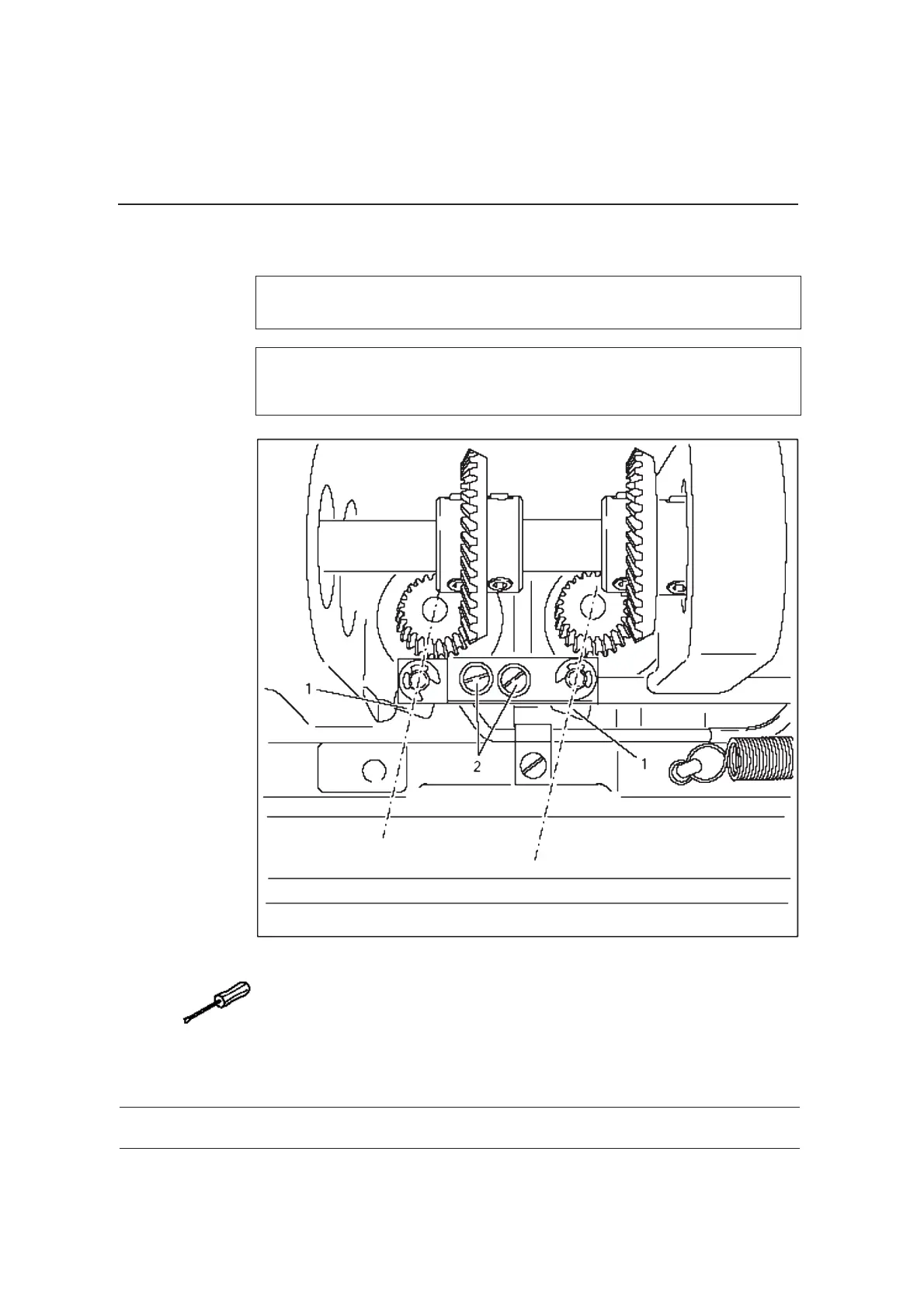
When the stitch length control device is locked in position, and the maxi-
mum stitch length is set, the marking line of the highest number on the
scale disk must be opposite the lower edge of the belt guard recess.
● 。
●
( )。
●
●
1 2
1 2 Requirement
Set the maximum stitch length.
Turn the scale disk (screw ) according to the .
3
1
2
9-19
Adjustment
9.04.09
Linkage rod
( )9620
(only for the 9620)
9.04.09
Linkage rod
( )9620
(only for the 9620)
9-44
Adjustment
, 。1
, 。1
Requirement
1When the thread trimmer is in its resting position, the drive levers must be
parallel.
Requirement
1When the thread trimmer is in its resting position, the drive levers must be
parallel.
● ( )。
●
12
1 2 RequirementAdjust drive levers (screw ) in accordance with the .
● ( )。
●
1 2
1 2 RequirementAdjust drive levers (screw ) in accordance with the .
9.03.16
Shaft crank to feed wheel drive
, (
)。
3
3 4
9625 9610
Requirement
3 3
4
When the maximum length is set, the linkage rod , or lingkage rods
and on the model 9625 and 9610, must be able to move freely when the
balance wheel is turned.
● 。
●
( )。
●
●
1 2
1 2 Requiremen
Set the maximum stitch length.
Twist or shift the shaft crank ( screw ) according to the t.
9-20
Adjustment
9625
9610
9620
9.04.08
Releasing the tension
Adjustment
9-43
, 。1. 3 0.5 mm
Requirement
3 0.5 mmWhen the magnet is activated, tension discs must be at least
apart.
● 。
● 。
●
●
1 2
1 2
Activate the magnet.
Detach the tension bearing plate and adjust pressure plate .
19 0* 260 6 14
Zj 96 10、9620、9625、9630
08 .0 4.2
 Loading...