Do you have a question about the JRC JHS-32A and is the answer not in the manual?
Provides guidance on managing individuals affected by electrical shock.
Lists key initial actions and considerations for administering first aid.
Explains various symbols used in the manual for clarity.
Highlights critical safety information to prevent severe injury or death.
Notes potential risks of damage to equipment or minor injury.
Warning regarding misuse of distress call procedures.
Procedures for ending an active distress transmission.
Information on how the unit handles incoming distress calls.
Defines common terminology related to maritime radio and communication.
Details the primary functionalities of the JHS-32A VHF radiotelephone.
Outlines the key characteristics and advanced capabilities of the system.
Describes the fundamental setup and components of the JHS-32A system.
Lists the core components included in the main unit.
Details optional accessories and their model numbers.
Illustrates how different components connect to form the system.
Provides physical measurements for the main unit and accessories.
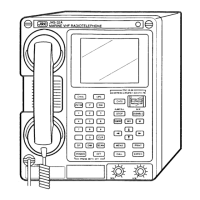
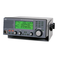
Identifies and describes the parts of the main VHF radiotelephone unit.
Explains the various displays and status indicators on the unit.
Covers fundamental communication procedures using the telephone mode.
Steps for powering the main unit and remote controllers on and off.
How to receive incoming calls and adjust audio settings.
Procedures for making outgoing transmissions.
How to establish communication on private channels.
Steps to store and recall frequently used channels.
Procedures for using stored memory channels for communication.
How to access and listen to weather broadcast channels.
Explains how to use the scanning function to monitor channels.
Overview of DSC call types and their characteristics.
Step-by-step guide to transmit distress alerts via DSC.
Procedures to cancel unintended DSC transmissions.
How the unit receives and displays DSC distress alerts.
Manually inputting location data for distress calls.
Relaying distress calls without modifying original data.
Manually entering position data when relaying a distress call.
Initiating a DSC call to all vessels in the vicinity.
Making a DSC call to a particular vessel or shore station.
Requesting a communication channel.
Connecting to public telephone services via DSC.
Acknowledging receipt of a DSC distress alert.
Manually acknowledging different types of DSC calls.
Viewing received DSC messages in real-time.
Accessing and reviewing stored DSC messages.
Saving telephone numbers for DSC communication.
Configuring automatic responses to DSC messages.
Manually setting the unit's date and time.
Checking and confirming current system settings.
General guidelines for routine upkeep and checks.
Regular inspection tasks for optimal performance.
Specific checks for the antenna and its connections.
Explanation of error messages and their meanings.
Performing diagnostic tests on the unit's functions.
Guidance on identifying and resolving common issues.
Steps to diagnose and pinpoint equipment problems.
A systematic approach to finding the root cause of malfunctions.
Detailed technical specifications for the main unit.
Technical specifications for the receiver component.
Lists of assigned channels for different regions and purposes.
Standard ITU channel allocations.
Channel assignments specific to the USA.
Channel assignments specific to Canada.
Channels designated for weather broadcasts.
Channels reserved for private communication.
Information about optional accessories for the system.
Specifications and operation of the remote controller.
Specifications for the connected printer.
Specifications for the guard receiver.
Details on data interfaces for GPS and time synchronization.
Detailed operation of the remote controller.
Installation and operation of handset connection boxes.
Operational guidelines for the NKG-52 printer.
| Output Power | 25 W / 1 W |
|---|---|
| Power Supply | 13.2 V DC |
| Operating Temperature | -15°C to +55°C |
| Type | Marine VHF Radio |
| Emission Modes | G3E, G2B |
| Number of Channels | 55 |
| Modulation | 16K0G2B |