Do you have a question about the JRC JSS-296 and is the answer not in the manual?
Overview of the GMDSS Console system configuration, showing component relationships.
Detailed interconnection diagrams for various GMDSS Console models.
Guidelines for choosing an optimal location for the antenna system.
Procedures and considerations for installing the MF/HF radio equipment.
Step-by-step guide for initial settings of various units in the system.
Initial setting procedures for the Power Amplifier, including charge and voltage settings.
Setting up Self ID, Navigation, and Radiotelephone parameters for the modem.
Procedures for setting up NBDP mode on the Data Terminal.
Operation checks and user channel/group registration for the Radiotelephone.
Troubleshooting guide for common issues with the JSB-196GM.
Troubleshooting steps for issues related to the NCT-196N modem.
Troubleshooting for no display on the LCD of the Power Amplifier.
| Frequency Range (Transmit & Receive) | 1.6 to 27.5 MHz |
|---|---|
| Output Power | 150W (PEP) |
| Emission Modes | J3E, H3E, F1B, A1A |
| Channels | 199 user-programmable channels |
| Power Supply | 24 V DC |
| Dimensions | 360 x 360 x 100 mm (Transceiver Unit) |
| Weight | 10 kg (Transceiver Unit) |
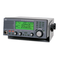
| Type | MF/HF Radio |
| Frequency Range (Receive) | 0.5-30 MHz |
| Tuning | Synthesized |
| DSC | Class A DSC |
| Modulation | J3E, H3E, F1B, A1A |