6.2.1 Descriptions
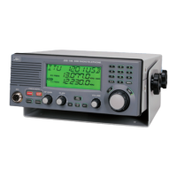
The JSB-196GM consists TRX unit type CMN-1960, PA unit type CMN-1960 and Control unit
type CDJ-1960.
The Control unit consists the CPU, audio amplifier for handset microphone and 1500Hz test tone
generator. The CPU controls the TRX unit, PA unit and input/output signals from/to connected
units.
TRX unit consists AF block, IF block, RF block, DSP block and SYNTH block. The TRX unit
uses the there kind of IF signals 70.455MHz, 455KHz and 20.22KHz for reception and
transmission. DSP block converts the 20.22KHz IF signal to audio frequency. SYNTH block
makes the 70.555 – 100.455MHz 1
st
local frequency and 70MHz local frequency. AF block
selects the input signal to the DSP block. During DSC and NBDP mode the line input is passed to
the DSP block, during TEL mode the microphone signal is passed.
PA unit amplifies the transmission signal to 1 – 2W during AC operation, to maximum 150W
during DC operation, and to about 10W during tune.
6.2.2 Signals from/to the other units.
From/
To
Connecter
Name
Pin
No.
Signal
Name
Description
ANT RF OUT
Transmission signal output.
AC operation: 0 – 2 W
DC operation: 100 W max. (2 MHz), 150 W max. (4 – 25
MHz)
Console
terminal
(Console type NCU-324/1960)
1 TXD 85 Transmission data to the PA unit.
2 GND 86 Signal ground.
4 Analog 88 Antenna current analog data.
5 PA mute 89 Transmission is prohibited by low signal.
Tuner
6 RXD 90 Received data from the PA unit.
PA
(NAH-
692/
695/
698)
Accessory 10 -BK 87 Key signal to the PA unit.
Receive
antenna
RX ANT RF IN Receive signal.
13 Line in (+)
14 Line in (-)
Modulated audio frequency signal input for DSC and NBDP.
600 ohms 0 dBm (-20 -- +10 dBm)
15 GND Signal ground.
16 Line out (+)
Accessory
17 Line out (-)
Received audio frequency signal output for DSC and NBDP.
600 ohms 0 dBm (-20 -- +10 dBm)
2 RXD Reception data from the modem unit.
3 TXD Transmission data to the modem unit.
4 -BK Break signal output to mute the modem unit.
5 GND Signal ground.
6 EXT KEY External key signal input from the modem unit.
7 TX RDY JSB-196GM ready to transmit when low signal.
Modem
(NCT-
196N)
Modem
8 Scan Stop The modem unit stops the scanning when low signal.
87