3.2 MF/HF RADIO EQUIPMENT INSTALLATION
Do not place this equipment anywhere vibration or impact is likely to occur.
Doing so may cause a fall or damage to property and persons.
Do not install this equipment in a place near water or in one with excessive
humidity, steam, dust or soot. Doing so may cause fire, electric shock, or
malfunction.
CAUTION
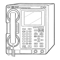
Install the JSS-296/596/896 MF/HF Radio equipment in a location that meets the following conditions:
・ A location with minimum vibration.
・ A location with sufficient ventilation.
・ A location 1.5 m or further from a magnetic compass.
3.2.1 AC and DC connections
JSS-296/596/896 is connected with power source by DPYCY cable. (Refer to Figure 3-2).
Figure 3-2 Power Cable connection
AC current
The maximum current is as follows.
Maximum current = JSS-296/596/896 + SES + VHF×2
It is as follows, in connecting JUE-75C as SES and connecting JHS-32B as VHF.
Maximum current of 220V operation (JSS-296)
= 7A (JSS-296) + 1.5A (SES:JUE-75C) + 1A×2 (VHF:JHS-32B)
=10.5A (220V)
DC current
The maximum current of DC24V is 40A.
Terminal block width
Even a 35mm
2
cable can connect with the Terminal block.
AC BATT
12
34
56
++ --
24V
Battery
GMDSS Console/NCU-692
Terminal block
DPYCY-xx
DPYCY-xx
+
-
UV
AC
DPYCY-yy
Terminal width:35mm
2
Maximum DC current:40A
17
 Loading...