3
3. OPERATION
3.1 Description
(1) Helical antenna
The flexible helical antenna is firmly assembled
with this radiotelephone. To remove the
antenna, exclusive wrench is required.
(2) Shoulder belt fittings
Fasten the attached shoulder belt to these
fittings before using the belt to carry the
radiotelephone.
(3) PTT(press-to-talk)button
Depressing the switch enables transmission,
and releasing it enables reception.
(4) Speaker
Produces received sounds.
(5) MIC (microphone)
Talk to the microphone during calling.
(6) PUSH button
Press this button to unlock the battery pack
when removing it.
(7) Battery pack NBB-248/248A/389
Supplies power to the radiotelephone. Section
3.3 describes how to replace the battery pack.
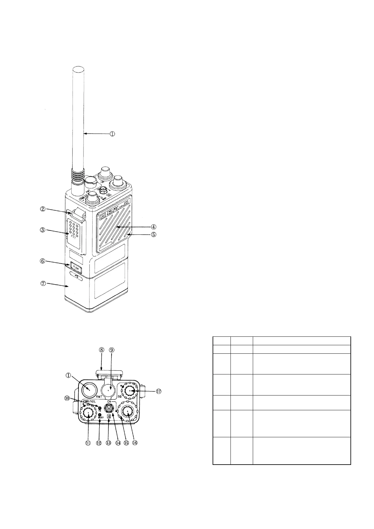
(8) Belt clip
Hold the radiotelephone with a belt.
(9) RMT(remote terminal) connector
Connect the optional earphone 6UMJD00004 or
external speaker/microphone 6UMJD00029.
During connecting here, the internal speaker is
automatically tuned off. Also when the external
speaker/microphone is connected, both the
internal speaker and microphone are turned
off. The pin assignments are as follows;
No. Name Function
1 E Ground of the radiotelephone.
2 EXT
PTT
Control line for external control
of PTT. Grounding it enables
transmission.
3 EXT
MIC
Input terminal for the external
microphone. It also outputs a bias
voltage for a condenser microphone.
4 EAR
F output (8Ω) for the earphone
and external speaker.
5 MIC
CONT
Control line for control of the
external microphone.
Grounding this terminal turns off
the internal microphone.
6 SP
CONT
Control line for control of the
internal speaker output.
Grounding this terminal turns off
the internal speaker.
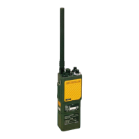
Figure 3-1 Appearance
Figure 3-2 Operation Panel