Do you have a question about the JRC JMA-2253 and is the answer not in the manual?
Warning about high voltages in radar devices and necessary precautions.
Risks from dust inhalation and microwave radiation exposure during operation and maintenance.
Immediate actions to take when a person is a victim of electric shock.
Detailed steps for providing artificial respiration and basic first aid.
Step-by-step guide for mouth-to-mouth resuscitation when breathing has stopped.
Procedures for cardiac arrest, including chest compressions and artificial respiration.
Crucial warnings about installation, operation, and potential inaccuracies.
Hazards related to rotating antennas and electromagnetic energy exposure.
Understanding the radar's role as an aid, not a sole reliance for navigation.
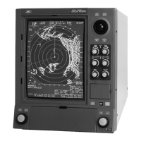
Introduction to the radar series, its features, and configuration details.
List and details of accessories provided with the radar system.
Key performance and environmental parameters of the radar system.
Detailed technical specifications for the scanner unit, including dimensions and performance.
Technical specifications for the display unit, covering dimensions, range scales, and controls.
Specifications for the rectifier unit and guidelines for unit-to-unit cable spacing.
Description of the radome antenna unit, its components, and radiator characteristics.
Description of the open array antenna unit, its mechanical and electrical features.
Explanation of the transmitter unit's modulator, pulse width, and PRF.
Description of the receiver unit's components, including the MIC front end and IF amplifier.
Simplified block diagram and overview of the display unit's main circuits.
Detailed functions of the main control PCB, including video processing and memory.
Functions of control PCBs, the graphic display controller, and video output circuits.
Description of the display monitor and handling of optional sensor inputs.
Explanation of the power supply unit's operation and voltage outputs.
Steps for performing a master reset to resolve operational issues.
Guidance on fuse inspection, replacement, and identifying fault causes.
General procedures and assumptions for fault diagnosis using test equipment.
Routine cleaning, screw inspection, and cabling checks for the radar system.
Maintenance procedures for the radome and rotary scanner units, including lubrication.
Instructions for cleaning the display unit's screen to ensure image clarity.
Fundamental principles and considerations for installing the radar unit.
Selecting the scanner unit location and following installation procedures.
Instructions for connecting cables to the redome and rotary scanner units.
Selecting the display unit location and performing installation steps.
Connecting power cables and interunit cables to the display unit.
Procedures for connecting external devices such as buzzers to the display unit.
Diagram and steps for connecting an electromagnetic compass to the display unit.
Required fuse rating modifications for the inboard power supply based on voltage.
Details of interunit cables, including types, lengths, and conductor functions.
Criteria for selecting power cables, considering voltage drop and current capacity.
Post-installation checks, functional verification, and initial adjustment items.
Instructions for changing input terminal connections on the rectifier unit for different AC voltages.
Adjustments needed when replacing major components like the magnetron or CRT.
Adjusting the modulator's AVR output voltage and transmitter pulse width.
Adjusting receiver gain, sea return, main bang suppression, and tuning indicators.
Adjusting display brilliance, focus, screen tilt, CRT settings, and AVR output voltage.
| Type | X-band Radar |
|---|---|
| Frequency | 9410 MHz ± 30 MHz |
| Output Power | 4 kW |
| Display Size | 10.4 inches |
| IP Rating | IPX6 |
| Range | 0.125 to 48 NM |
| Display | LCD |
| Antenna Length | 4 feet |
| Antenna Rotation Speed | 24 rpm |
| Range Resolution | 20 meters |