Do you have a question about the JRC JMA-7710-6 and is the answer not in the manual?
Explains various pictorial indications used in the manual and on equipment for safe operation.
Describes the warning label on the top cover of the equipment and advises against removal or modification.
Details warnings about touching high voltage areas, scanner rotation, and proximity to electric waves.
Advises using radar and ATA as assisting devices and making final decisions for maneuvering.
Details safety measures for high voltage in electronic equipment, including power off and capacitor discharge.
Provides instructions on how to respond to an electric shock victim, including power off and artificial respiration.
Outlines general first-aid steps for an electric shock victim, including artificial respiration and calling for help.
Illustrates and explains the method of performing mouth-to-mouth respiration by raising the head.
Details how to perform artificial respiration when pulse is present but breathing has stopped.
Provides instructions for Cardiopulmonary Resuscitation (CPR) when both pulse and breathing have stopped.
Details the functions of the radar and optional ATA system, including target detection and collision avoidance.
Describes key features like display quality, signal processing, ease of operation, and optional ATA capabilities.
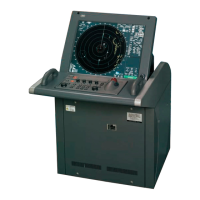
Details the equipment components, including radar types, scanner units, display units, and their specifications.
Provides outline drawings of the scanner and display units, referencing figures for detailed dimensions.
Illustrates the system connections between scanner units, display units, and other equipment.
Explains the necessity and basic concepts of collision avoidance, including navigation patterns and collision triangles.
Details the controls and keys on the display unit's control panel, including safety cautions.
Explains the menu composition, selection process, and lists available main and sub menus for system functions.
Provides a step-by-step flow of basic operation, from power-on to stopping the system.
Details essential preparation steps including tuning, adjusting sensitivity, CRT brilliance, and clutter suppression.
Covers fundamental operations like using the trackball, EBL, range scales, pulse width, presentation modes, and motion displays.
Explains how to use the function key for selecting preset radar signal processing modes and changing settings.
Details how to display shoreline ROM cards, ERC cards, and JRC charts for navigation.
Explains how to change track color, select storing intervals, stop storing, and delete tracks by color.
Covers creating, deleting, and displaying navigation lines, marks, and comments, including chart position adjustment.
Details how to use the trackball to measure range and bearing to a target on the screen.
Explains how to use fixed range rings to estimate the range of targets by percentage.
Describes how to use the Electronic Bearing Line (EBL) and Variable Range Marker (VRM) for precise measurements.
Explains how to measure the distance and bearing between two optional points using EBL and VRM.
Explains how to initialize the ATA, including setting collision judgment conditions like CPA and TCPA limits.
Covers setting the motion display mode (TM/RM) and bearing display mode (AZI MODE) for ATA data.
Details automatic and manual target acquisition methods using the guard zone and cursor, including target numbering.
Explains how to select vector modes (True/Relative) and set vector length for displaying target forecast positions.
Describes how to display numerical data readouts for targets, including ID, bearing, range, CPA, and TCPA.
Details the ATA alarm system, including dangerous target alarms (CPA/TCPA), guard zone alarms, and lost target alarms.
Explains how to erase individual targets or all targets from the ATA system.
Describes how to adjust the brilliance of ATA symbols and graphic data through the main menu.
Details how to perform function checks for ATA, including vector constant and video level settings.
Explains how to set up and manage target past tracks, including function, color, display, interval, and storage.
Describes how to turn the display and non-display of ATA symbols and target data on or off.
Explains how to enable or disable audible warnings for dangerous and lost targets in the ATA system.
Details how to use the simulation mode to display a pseudo target for checking ATA functionality.
Explains the radar line-of-sight range formula and factors affecting it, such as antenna and target height.
Discusses how target material, shape, height, and size affect echo return strength and coastal line display.
Describes the appearance of sea clutter on the screen related to sea conditions and wave strength.
Explains causes of false echoes, including shadow effect, side lobes, secondary reflection, and anomalous propagation.
Details how to display SART signals and the necessary settings for radar operation.
Covers routine maintenance tasks such as cleaning the radar body and ATA, emphasizing safety precautions.
Provides maintenance procedures for the scanner unit (window, gears, motor) and display unit (CRT surface).
Details regular checks and menu-based diagnostic tests for the radar system, including memory and sensor tests.
Lists common failure statuses and their probable causes, along with a check list for troubleshooting.
Provides specific troubleshooting steps for radar and ATA issues, including causes and corrective actions.
Details procedures for replacing major components like the magnetron and other parts in scanner units.
Covers adjustments and settings required after installation, including NSK unit, tuning, bearing, range, and antenna height.
Provides guidance on what information to provide when requesting repair, and procedures for warranty and post-warranty service.
Recommends periodic maintenance inspections to ensure optimal performance and prevent issues.
Instructs to dispose of equipment according to local authorities' ordinances and regulations.
Provides safety warnings and procedures for disposing of used lithium batteries, emphasizing insulation and local regulations.
Advises returning used magnetrons to a local distributor or sales office for proper disposal.
Lists general specifications for JMA-7710-6, JMA-7725-6, and JMA-7725-9 models, covering emission, display, ranges, and conditions.
Details technical specifications for the NKE-1055-6 scanner unit, including dimensions, mass, beam width, and output.
Details technical specifications for the NKE-1056-6M/9M scanner units, including dimensions, mass, beam width, and output.
Provides technical specifications for the NCD-3901-2 display unit, covering structure, dimensions, pixels, and color/gradation.
Lists specifications for the optional ATA NCA-843, including acquisition, tracking range, data display, vector, and alarms.
Details the types of navigation and gyro signals that can be input into the system.
Lists the external alarm, sub display unit, and remote monitor signals that can be outputted.
Lists the standard included equipment, such as scanner unit, display unit, cables, and manuals.
Specifies the recommended clearance distances between scanner, display, and performance monitor units.
Lists optional features like ATA function, plotter function, and specific cables.
Lists circuit codes for various components of the radar system, categorized by general code, scanner unit, and performance monitor.
Presents the circuit diagram for the JMA-7710-6 and JMA-7725-6/9 radar types.
Illustrates the terminal board connection diagram for the JMA-7710-6 radar type.
Illustrates the terminal board connection diagram for the JMA-7725-6/9 radar types.
Shows the primary power supply system diagram for the JMA-7710-6 and JMA-7725-6/9 radar types.
Details the internal connection diagram for the NKE-1055 scanner unit.
Details the internal connection diagram for the NKE-1056 scanner unit.
Details the internal connection diagram for the NCD-3901-2 display unit.
Illustrates the power supply connection diagram for the NCD-3901-2 display unit.
Shows the NSK log selection switches and their settings for the NCD-3901-2 display unit.
Provides the setting table for speed log select switches on the NCD-3901-2 display unit.
Details the setting table for gyro compass and gyro select switches on the NCD-3901-2 display unit.
| Brand | JRC |
|---|---|
| Model | JMA-7710-6 |
| Category | Marine Radar |
| Language | English |