Do you have a question about the JRC JMA-7725-6 and is the answer not in the manual?
Explains visual symbols used in the manual and on equipment for safety.
Highlights the presence of a warning label on the equipment's top cover.
Details safety measures for high voltage components during maintenance.
Provides emergency procedures for handling electric shock victims.
Outlines immediate steps to take for victims of electric shock.
Details artificial respiration techniques for victims with pulse but no breathing.
Explains cardiac massage and CPR procedures for victims with no pulse or breathing.
Describes the core capabilities and operational principles of the radar system.
Lists key characteristics like display quality, signal processing, and user interface.
Details the main components and spare parts included with the equipment.
Provides outline drawings and dimensions for scanner and display units.
Illustrates the interconnections between the radar system components.
Explains the principles and methods used for preventing ship collisions.
Identifies and describes the purpose of each control and key on the display panel.
Details how to navigate and select options within the radar's menu system.
Outlines the sequence of steps for starting, operating, and shutting down the radar.
Covers essential setup procedures like tuning, sensitivity, and clutter control.
Explains fundamental functions like using cursors, EBL, VRM, and display modes.
Describes how to utilize preset function modes for optimized radar performance.
Details how to display navigational charts from ROM and ERC cards.
Explains how to manage and display the vessel's track history.
Covers creating, displaying, and deleting navigation aids like lines and marks.
Explains how to use the trackball for target measurement on the screen.
Describes how to use fixed range rings for distance estimation.
Details using EBL and VRM for precise range and bearing measurements.
Explains measuring distance and bearing between two selected points.
Covers setting up the ATA system, including collision judgment conditions.
Explains how to select between True Motion and Relative Motion display modes.
Details methods for acquiring and tracking targets automatically or manually.
Explains how to display target vectors, past positions, and data readouts.
Describes how to view target identification, bearing, range, CPA, and TCPA.
Details the types of alarms (CPA/TCPA, Guard Zone, Lost Target) and their conditions.
Explains procedures for deleting individual targets or all tracked targets.
Covers adjusting the brilliance of ATA symbols and graphics.
Details how to perform checks on ATA functions like vector constant and video levels.
Explains storing, displaying, and managing past track data for targets.
Describes how to enable or disable the display of ATA symbols and target data.
Covers enabling or disabling audible alarms for dangerous and lost targets.
Explains how to use the simulation function to test ATA performance.
Explains the factors affecting radar range and provides a calculation formula.
Discusses how target characteristics influence echo strength and display.
Describes the appearance and causes of sea clutter on the radar display.
Details various types of false echoes like shadow effect, side lobe, and reflections.
Explains how to display SART signals and related settings.
Covers essential cleaning procedures for the radar and ATA units.
Provides maintenance guidelines for scanner and display units.
Details procedures for checking radar functions and testing system components.
Lists common failures and their probable causes, including fuse checks.
Offers guidance on identifying and resolving radar and ATA system issues.
Provides step-by-step instructions for replacing key components like magnetrons.
Covers essential adjustments after installation, including tuning, bearing, and GPS settings.
Guides users on procedures and information needed when requesting product repair.
Advises on periodic maintenance inspections to ensure optimal performance.
Instructs on proper disposal procedures according to local regulations.
Details safety precautions and disposal methods for lithium batteries.
Provides instructions for returning used magnetrons for disposal.
Lists general technical specifications for the radar models.
Provides detailed technical specifications for the NKE-1055-6 scanner unit.
Details technical specifications for the NKE-1056-6M/9M scanner units.
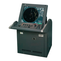
Lists technical specifications for the NCD-3901-2 display unit.
Specifies the features and capabilities of the optional ATA unit.
Lists the types of signals the system can receive from navigation equipment.
Lists the types of signals the system can output to other devices.
Outlines the standard components included with the radar system.
Provides recommended spacing for equipment installation.
Lists optional accessories and features available for the system.
Provides a list of circuit codes used in the radar system.
Shows the overall circuit diagram for the radar models.
Details terminal board connections for the JMA-7710-6 radar.
Details terminal board connections for the JMA-7725-6/9 radar.
Illustrates the primary power supply system for the radar models.
Shows internal wiring connections for the NKE-1055 scanner unit.
Shows internal wiring connections for the NKE-1056 scanner unit.
Illustrates internal wiring of the NCD-3901-2 display unit.
Details the power supply connections for the NCD-3901-2 display unit.
Explains the NSK log selection switches on the NCD-3901-2 display unit.
Provides a table for setting speed log select switches on the display unit.
Details gyro compass and select switch settings for the display unit.
| Brand | JRC |
|---|---|
| Model | JMA-7725-6 |
| Category | Marine Radar |
| Language | English |