2-34
JMA-9100/7100 Installation Manual > 2.INSTALLATION OF SCANNER UNIT > 2.4 PRECAUTIONS
• To avoid interference with other equipment and to prevent radio noise from generating,
do not place the VHF antenna, GPS antenna, and INMARSAT's dome within the range
of the vertical beam width.
• Keep a record of installation height data. The data is necessary for the initial setting of
the display unit.
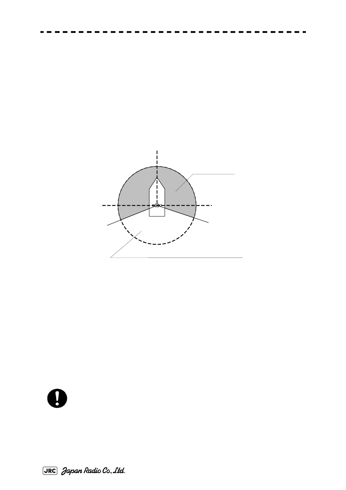
• Minimize the blind sector, and ensure the adequate view angle so that the blind sector
does not exist in the range 22.5 from side to rear (Fig 2-27). Specifically, ensure a
sufficient view field in the straight front (relative bearing 000 ).
• Individual blind sectors of more than 5, or a total arc of blind sectors of more than 20,
should not occur in the remaining arc, excluding the arc in Fig 2-27.
• For radar installations with two radar systems, where possible, the antennas should be
placed in such a way as to minimize the blind sectors.
Fig 2-27: Ensuring view angle
• Magnetron which has strong magnetic force is included in the scanner. Install the
scanner at least 6 meters away from nautical instruments including magnetic compasses
and chronometers.
*If there is a concern that structural objects existing within the vertical beam width may generate
false echo, equip the structural objects with a radio wave absorber. (There are two types of
absorbers: broadband type having no specific resonant frequency and narrowband type which
can absorb a band with a specific frequency. Use those where applicable.) Furthermore, it is
effective to install a metal reflector, which reflects radio waves upwardly, between the scanner
and a structural object so that the radar's radio wave will not directly come in contact with the
structural object.
When the structual objects exist in the surrounding area of Scanner unit, the false echo may
appear. The sector blank function is effective to reduce the signal reflection from the structual
objects. Because it can stop transmission. Therefore, it may reduce the false echo appearance.
*The above procedures for selecting an scanner installation position are described based on the
radar's scanner. Comprehensively select the scanner position by considering other scanners'
installation procedure manual, hull's structure, strength of the selected position, and vibration.
Because most radio wave absorbers have poor durability, some must be replaced
every year. When installing a reflector, the area to the rear of the reflector becomes
a blind sector. Therefore, minimize the size of the reflector.
When the sector blank function set to on, ensure a sufficient view field in the
straight front.
22.5°22.5°
Make no blind sector
Individual blind sectors of more than 5
°
, or a total arc of blind
sectors of more than 20
°
, should not occur in the remaining arc.
Heading
0°direction
 Loading...


