JMA-9100 Instruction Manual > 7.SETTINGS FOR SYSTEM OPERATION > 7.1 SETTINGS AT INSTALLATION
7-3
7
4) Set the DIP switch S2.
The items to be set are listed below. For the setting, refer to Table 7-2: Gyro and Log Select
Switches (S2 DIP Switch).
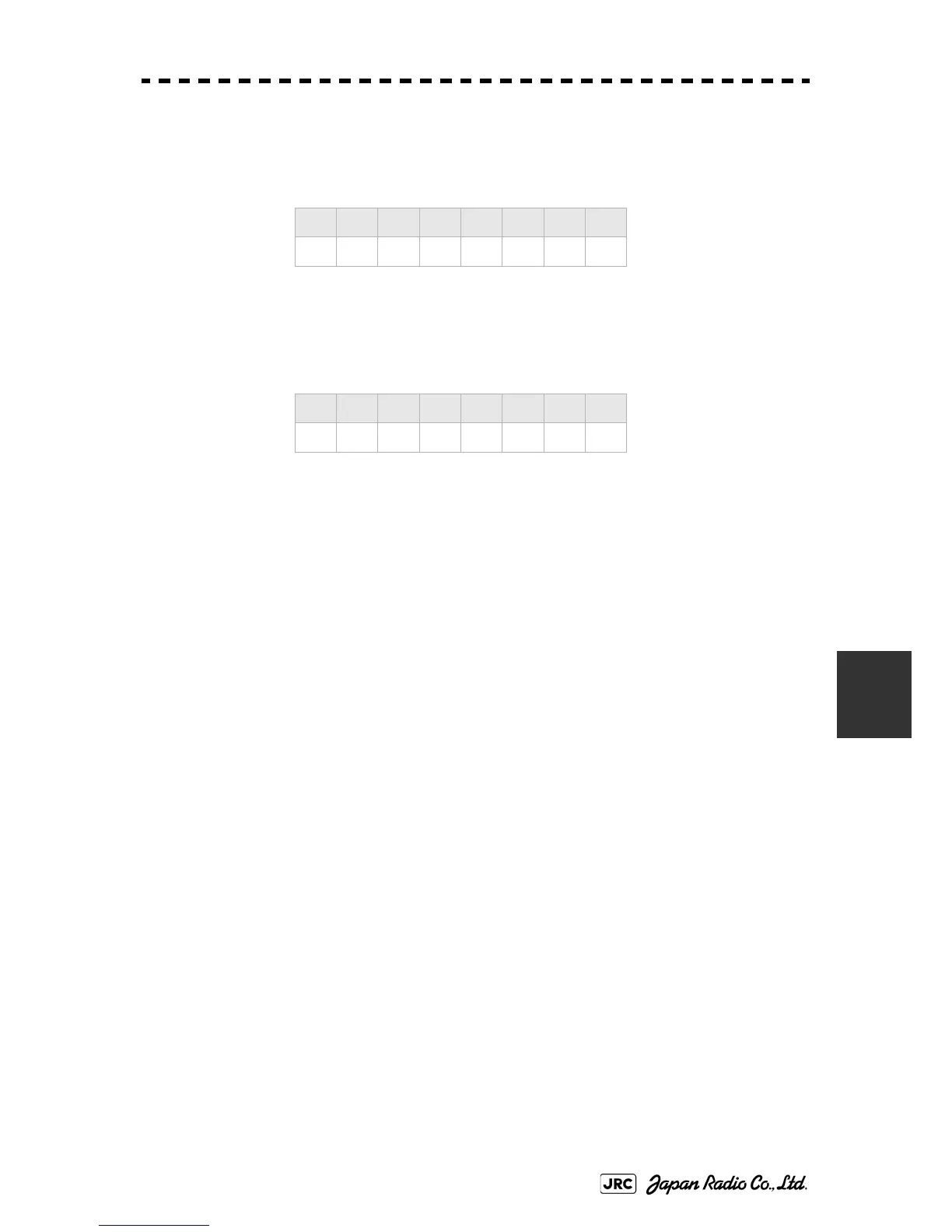
5) Confirm the settings of the DIP switch S10.
The DIP switch must be set as shown below. Do not change any of the settings.
6) Set the jumper TB105.
The TB105 is set for using a low-voltage step signal.
7) Connect the gyro signal and log signal cables to the terminal
block.
8) Set S5 to "ON".
The gyro compass and GYRO I/F are connected.
9) After power-on operation, make sure of the radar video and the
operation with the true bearing value.
See the Section 7.1.7 "Setting of True Bearing Value".
10) If the true bearing value of the radar equipment is reversed,
change the setting of the switch S1-4.
1 2 3 4 5 6 7 8
ON OFF OFF OFF ON OFF ON OFF
1 2 3 4 5 6 7 8
OFFOFFOFFOFFOFFOFFOFFOFF
1-2 connected: Setting for normal use
2-3 connected: Setting for a step signal of 22 V or less
 Loading...


