8-26
JMA-9100 Instruction Manual > 8.COUNTERMEASURE FOR TROUBLE ... > 8.4 REPLACEMENT OF MAJOR PARTS
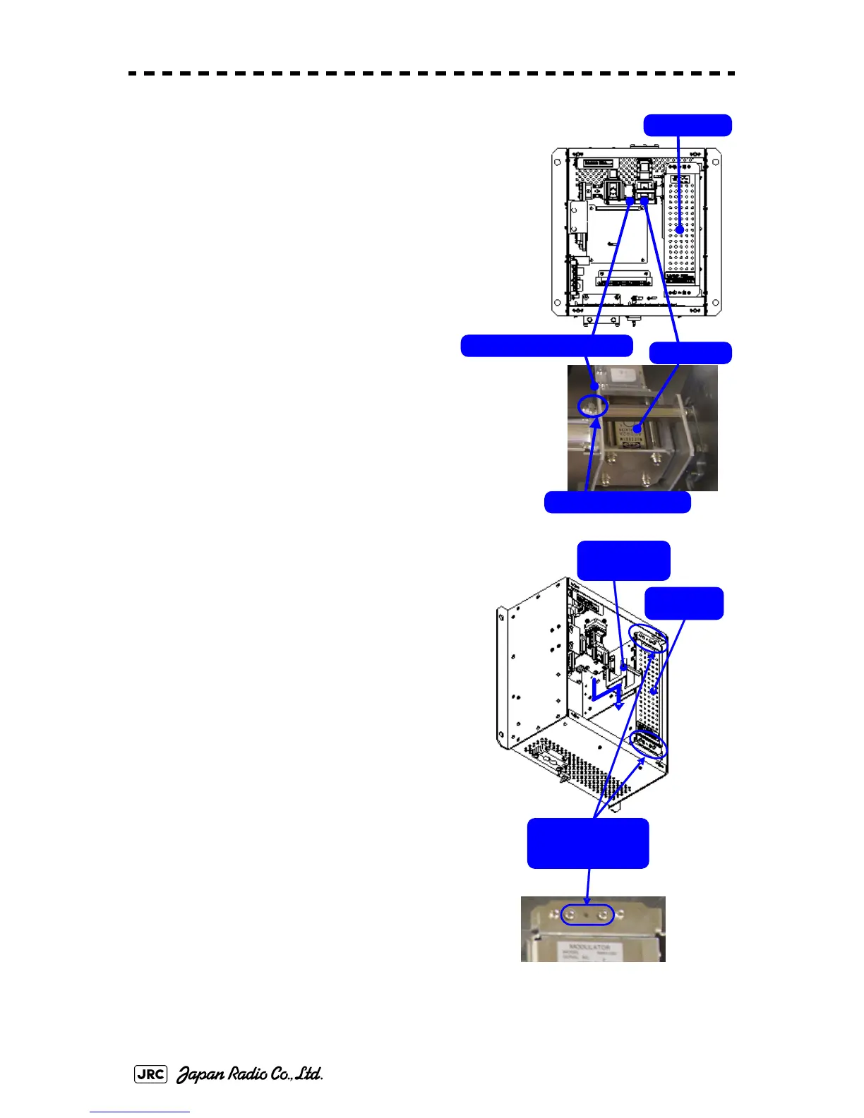
2) Loosen the upset head bolt (one M4 bolt),
and slide the tightening metal fitting,
located between the modulator and the
circulator, to remove it.
The magnetron is installed within the
modulator.
3) Loosen the inside screws of the modulator
(four M4 screws).
Removing the outside screws makes it possible
to slide the modulator.
Tightening metal fitting
Circulator
Modulator
Remove the screw.
Loosen the four
screws.
Tightening
metal fitting
Modulator

 Loading...


