JMA-9100 Instruction Manual > A.NQE-3141 Interswitch Unit > A.3 REFERENCE
A-11
A
pulse length, the range of the slave display unit may be forcibly changed. In this
case, is shown in the alarm indication (lower right of the
display), and the alarm sounds.
A.3.4 Setting at Installation
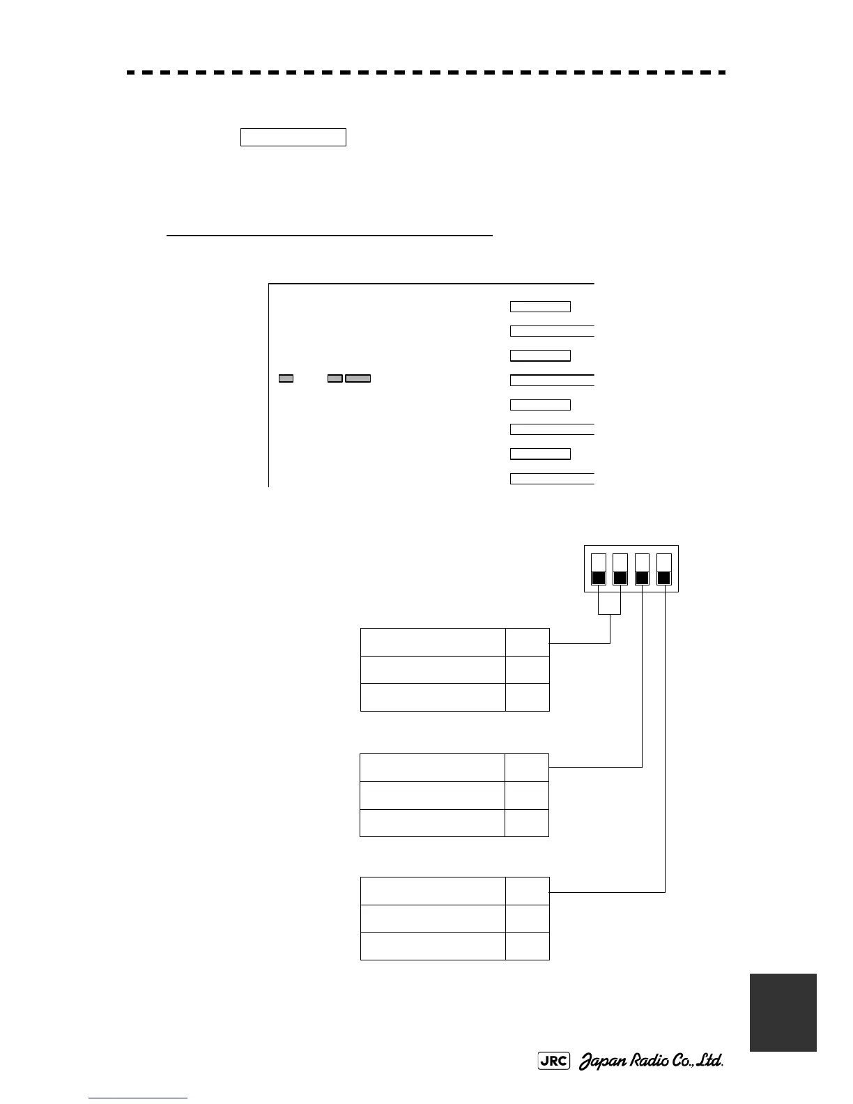
Setting of the interswitch circuit (CCL-304*)
The settings of the DIP switches SW11 to SW13 are shown below.
1) SW11 setting (extension mode and master/slave settings)
Master Range CHG
SW 11
SW 13 SW 12
Interswitch circuit PCB
CCL-304*
4Description
Extension mode setting
ONExtension mode
OFFNormal mode
3Description
ONSlave
OFFMaster
1, 2Description
ONUnused
OFFUnused
Unused
Master/slave setting
Set the switch to OFF if the
number of connected display
units is four or less .
Set the switch to ON if the
slave ISW PCB is selected in
extension mode.
Set the switch to OFF in
normal state.
1234
ON
OFF

 Loading...


