2-21 Chapter 2 System Configuration
The function system diagram of Display Unit is shown in Fig. 2.3.4 and Fig. 2.3.5
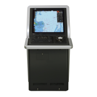
Display Unit is composed of following units:
MNU : Monitor Unit NWZ-208 (26inch)
NWZ-207/214 (19inch)
CCU : Central Control Unit NDC-1590
PSU : Power Supply Unit NBD-913
TOPU : Trackball Operation Unit NCE-5605
KOPU : Keyboard Operation Unit NCE-5625(*)
Sensor LAN Switch Unit NQA-2443(*)
JB : Junction Box NQE-1143(*), (**)
(*) Option.
(**) JB may include following circuits and they depend on the system:
SLC : Serial LAN Interface Circuit CMH-2370
AOC : Analog Option Circuit CMJ-560
GIF : Gyro Interface Circuit CMJ-554
RIF : Radar Interface Circuit CQD-2273
Starting the system
Turning on the power switch of TOPU starts PSU, 24Vdc (MNU) and 24Vdc (CCU) are supplied
to MNU and CCU respectively. After starting its OS up, CCU initializes the various parameters and
DSPs and it provides the functions such as Radar processing and display function, Electronic
Chart Display function, Ship's sensors Information display function and more.
After that, CCU sets the internal status according to the sensor data input from the various
communication lines, such as the GYRO and GPS, and issues an initialization command to the
transmitter-receiver unit via the communication line to initialize the transmitter-receiver unit. This
concludes the initialization of the system.
Circuit functions
Operation circuit detects the operating status of the switches and dials of the TOPU and KOPU
and sends the operation data to the CCU through the communication line.
SLC : Serial LAN Interface Circuit converts serial signals sent by ship's various sensors into
LAN data packets. It sends that signal to CCU via an Ethernet cable.
AOC : Analog Option Circuit mediates Ship's analog sensor signals to CCU via SLC. It has
four input ports. You can choose the kind of input type for each port which are -10V to 10V voltage
input or 4-20mA current loop input.
GIF : Gyro Interface Circuit processes the gyro signal, which is in the synchro or step format,
calculates the true azimuth, and sends the true azimuth data to the radar processing circuit at
regular intervals using serial communication. As long as the GIF circuit is receiving the gyro signal,
 Loading...