12.11 SPD1 SPD2 SPD3 Internal speed switching inputs (CN1-32~35)
ELGN1 ELGN2 ELGN3 Electronic Gear Numerator Switching Inputs (CN1-32~35)
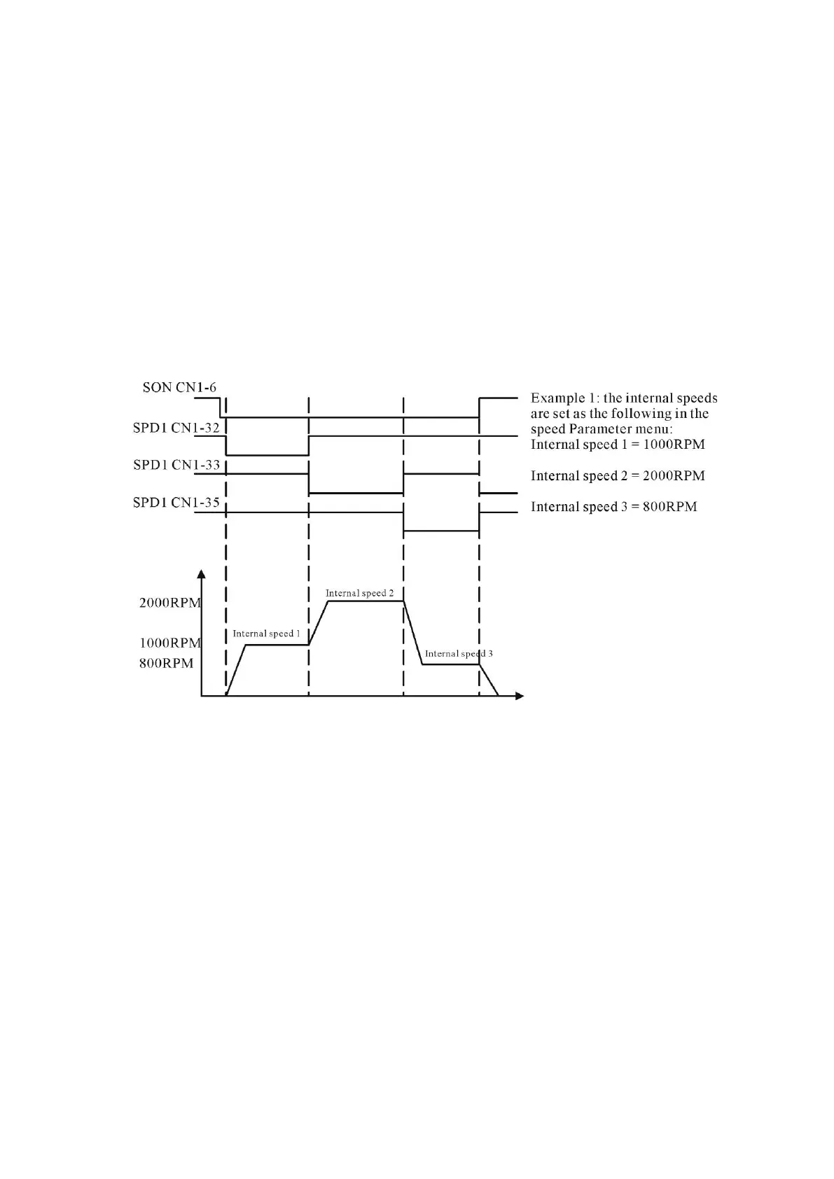
When the servo drive is in S Mode or switched to Speed operation mode, and if the internal speed is
enabled, the internal speed command can be selected by properly connecting one among CN1-32 (SPD1),
CN1-33(SPD2) and CN1-35(SPD3) to 24G. The three pins correspond to three different internal speed
commands which are defined by the parameters Internal Speed 1, Internal Speed 2 and Internal Speed 3
(Unit: RPM) in the “Speed Parameter”menu.
When the servo drive is in P Mode or switched to Position operation mode, the numerator of the
electronic gear ratio can be selected by properly connecting one among CN1-32 (ELGN1), CN1-33
(ELGN2) and CN1-35 (ELGN3) to 24G. The three pins correspond to three different numerators that are
defined by the parameters Numerator 1, Numerator 2 and Numerator 3 in the “Position Parameter”
menu, where a common denominator of the electronic gear ratio is also programmed
.
 Loading...