06
4. Part Identification & Accessories
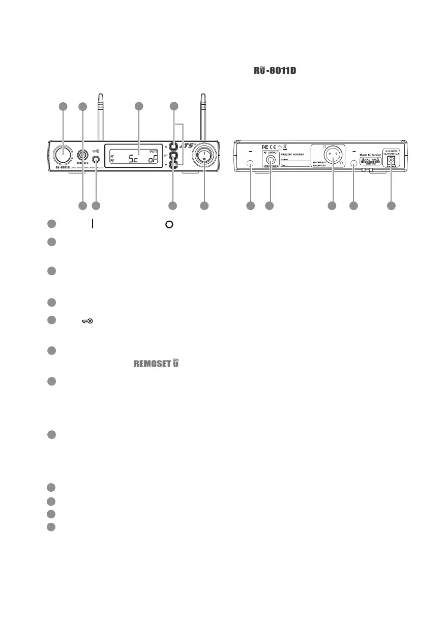
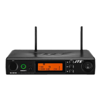
4-1-1 UHF PLL single-channel diversity receiver //
Front panel
1
3
25
7
Rear panel
4
8
6
100mA
12V out
Antenna A
100mA
12V out
Antenna B
129
10
11 9
1
4
2
5
3
6
7
8
Receiving antenna: xed antenna of 1/4 wave length
6.3mm phone jack: unbalanced audio output jack
3P XLR male: balanced audio output jack
DC power socket: for 12~15V DC / 300mA power supply
10
12
11
9
Power: means “ON” and means “OFF”
SET: this is for function settings. Push and hold for 2 seconds to enter the
setting mode. Push “SET” repeatedly to search for the function you wish to set.
▲/▼In the setting mode, push▲/▼to change the function parameter
In the non-setting mode: push▲/▼to adjust volume
LCD display
Lock :push and hold “Lock” for 2 seconds to lock the buttons in order to
prevent pushing any button by accident.
Remoset u : this allows user to synchronize the transmitter after modifying a
parameter. Push “ ” to synchronize the settings to the transmitter.
Remoset indicator : this shows the current pairing status. It ashes rapidly
when data is being transmitted and the ashing stops when the synchroniza-
tion is completed. However, the ashing slows down if synchronization fails
after a period of time of pairing attempt.
Ultrasonic transmission unit: it transmits digital pairing data at ultrasonic
frequency. When setting, direct the ultrasonic receiving element of the micro-
phone to the ultrasonic transmitting unit of the receivers. The eective range
is 30º on both sides with the optimized distance at 30cm.