EasyManua.ls Logo

JUKI CP-180 - User Manual

JUKI CP-180
21 pages
Print Icon
To Next Page IconTo Next Page
Loading...
ENGLISH
CP-180
INSTRUCTION MANUAL

Other manuals for JUKI CP-180

Question and Answer IconNeed help?

Do you have a question about the JUKI CP-180 and is the answer not in the manual?

Summary

Installing the Control Panel

Safety Precautions for Panel Installation

Warnings and precautions to prevent injury during panel installation.

Connecting the Control Panel Cord

Control Panel Configuration

Machine Head Setting Procedure

Selecting Machine Head Type

Procedure for selecting the correct sewing machine head model.

Machine Head Adjustment (Direct-Drive Motor Type)

Angle Adjustment Procedure

Steps for performing the angle adjustment of the machine head.

Control Panel Functionality

Counters, Compensation, and Information Access

Bobbin thread counter, needle compensation, and information switch functions.

Sewing Pattern Operation

Reverse Stitching Pattern Operation

How to select and configure the reverse stitching pattern.

Constant-Dimension Stitching Pattern

Overlapped Stitching Pattern

Rectangular Stitching Pattern

Production Support Function

Bobbin Thread Counter

Needle Up;Down Compensation Switch

Function Setting Switch

Optional Input;Output Settings

Pedal Sensor Neutral Point Compensation

Pedal Sensor Compensation Procedure

Steps to perform automatic compensation for the pedal sensor.

Auto Lifter Function Setting

Auto Lifter Function Activation

Procedure to turn on the auto lifter function and select solenoid or air drive.

Setting Data Initialization

Initialization Procedure

Steps to initialize all function settings and data.

Error Code Checking

Error Code Display and Checking

Procedure to turn on power with a switch pressed to display error codes.

Overview

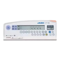
This document is the instruction manual for the JUKI CP-180 control panel, a precision instrument designed to enhance the functionality and efficiency of sewing machines. It covers installation, configuration, operation, and maintenance aspects of the control panel, emphasizing safety and proper usage.

Installation and Configuration

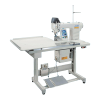
The CP-180 control panel is installed on the machine head using screws, flat washers, and a rubber seat. The specific screws required vary depending on the machine head model (e.g., DDL-9000A, DDL-9000B, LH-3500A). It's crucial to turn off the power switch and ensure the motor has completely stopped before installation to prevent personal injury. The control panel cord is routed through a hole in the machine table to the underside for connection to the control box.

The control panel features a power indicator lamp (LED) that lights up when the power switch is on, and a max speed limitation variable resistor to limit speed when moved to the left.

Machine Head Adjustment

For direct-drive motor type sewing machines, angle adjustment of the machine head is required before use. This involves simultaneously pressing two specific switches (1 and 2) while turning on the power. The indicator will display "ERJ" to signify adjustment mode. The handwheel is then turned by hand until an angle is displayed, indicating the detection of a reference signal. The white dot on the handwheel must be aligned with the concave part of the handwheel cover. Finally, pressing switch 4 completes the adjustment.

Control Panel Functions and Operation

The CP-180 control panel offers a wide range of functions for various stitching patterns and operational settings:

Stitching Patterns:

  • Pattern Selector Switch: Used to select from four different stitching patterns.
  • Reverse Stitching Patterns:
    • Double Reverse Stitching (for start/end): Switches to turn ON/OFF double reverse stitching at the start or end of a seam.
    • Automatic Reverse Stitching (for start/end): Switches to turn ON/OFF automatic reverse stitching at the start or end of a seam.
    • The number of stitches for processes A through D can be adjusted from 0 to 19 stitches using the "+" or "-" switches.
  • Constant-Dimension Stitching Pattern:
    • Allows selection of a constant-dimension stitching pattern, displaying predetermined stitches and reverse stitching function status.
    • Stitches for processes C and D can be changed from 5 to 500 stitches, while A and B remain 0 to 19.
    • Four different stitching patterns are possible by combining ON/OFF settings of automatic reverse stitching.
    • Double reverse stitching can also be specified.
    • If automatic thread trimming is ON, the machine trims thread after completing the specified stitches. If OFF, the touch-back switch can be used for low-speed stitch compensation.
    • Thread trimming prohibition stops the machine with the needle up without trimming.
    • One-shot automatic stitching performs sewing at a stretch at a specified speed.
  • Overlapped Stitching Pattern:
    • Selects an overlapped stitching pattern, displaying stitch count and repeated processes.
    • Stitches for processes A, B, and C can be changed from 0 to 19.
    • The number of repeated processes (D) can be changed from 0 to 9 times.
    • The machine automatically repeats normal and reverse stitching, then trims thread and stops.
    • Thread trimming prohibition stops the machine with the needle up.
  • Rectangular Stitching Pattern:
    • Selects a rectangular stitching pattern, displaying stitch count and other sewing data.
    • Stitches for processes A and B can be adjusted from 0 to 19, and C and D from 0 to 99.
    • Four different stitching patterns are possible with automatic reverse stitching ON/OFF settings.
    • Double reverse stitching can also be specified.
    • The machine stops after each step. Touch-back switch allows low-speed stitch compensation.
    • Automatic thread trimming trims thread after the last process.
    • Thread trimming prohibition stops the machine with the needle up.
    • One-shot automatic stitching performs sewing at a stretch at a specified speed.
    • For machines with an auto-lifter, the presser foot automatically goes up after each sewing process.

Counters and Switches:

  • Switches for Setting the Number of Stitches: Used for processes A through D.
  • Material Edge Sensor ON/OFF Switch: Activates when a material edge sensor is installed, allowing the machine to stop or trim thread upon detection.
  • One-Shot Automatic Stitching Switch: Starts automatic sewing until the material edge is detected or a constant-dimension stitching is completed.
  • Automatic Thread Trimming Switch: Automatically actuates the thread trimmer when the machine stops or the material edge sensor is used.
  • Thread Trimming Prohibition Switch: Temporarily disables the thread trimming function.
  • Bobbin Thread Counter/Thread Trimming Counter:
    • Bobbin Thread Counter: Indicates remaining bobbin thread by subtracting from a set value. If a detecting device is installed, it counts detections.
    • Thread Trimming Counter: Adds a value each time thread trimming is performed.
    • Bobbin Counter Reset Switch: Resets the bobbin thread counter to its initial value (0).
    • Bobbin Thread Amount Setting Switch: Sets the initial amount of bobbin thread. The initial value should be adjusted based on material thickness and sewing speed.
  • Needle Up/Down Compensation Switch: Performs needle up/down compensation stitching. Pressing this switch while turning on power changes the needle bar stop position (up/down) in neutral pedal position.
  • Information Switch: Calls up production support functions and one-touch settings.

One-Touch Setting

Certain function settings can be easily changed in normal sewing mode. To enter the one-touch setting mode, hold switch 1 for one second. Switch 2 changes the set value, and switch 1 returns to normal sewing. The wiper function (8P) can be set to operate or not operate after thread trimming.

Production Support Function

This function includes production volume management and operation measuring, each with different modes to enhance productivity and analyze performance.

Production Volume Management Function:

  • Target No. of pcs. display mode [F100]: Displays the target number of pieces.
  • Target/actual No. of pcs difference display mode [F200]: Displays the difference between target and actual pieces, along with operation time, to notify operators of delays or advances.
    • Detailed settings (F101, F102) allow changing the number of thread trimmings per garment and setting a target achievement buzzer.

Operation Measuring Function:

  • Sewing machine availability rate display mode [F300]: Displays the availability rate.
  • Pitch time display mode [F400]: Displays the pitch time.
  • Average number of revolutions display mode [F500]: Displays the average number of revolutions.
    • These modes measure and display sewing machine availability status, providing basic data for process analysis, line arrangement, and equipment efficiency checkup.

To display these modes, hold switch 1 for one second, then press switch 2 to show/hide them. Switch 3 selects the mode, and switch 4 changes ON/OFF display. Switch 1 returns to normal sewing. Data can be reset using switch 6 (held for 2 or 4 seconds).

Key Lock Function

To prevent accidental changes to stitch counts or process data (A, B, C, D), the setting switches can be locked. This is done by turning off the power, then turning it on while simultaneously pressing the automatic reverse stitching (for end) switch 1 and the "+" switch of number of stitches setting switch 2 for process A. A key mark on the control panel indicates the keys are locked. Repeating the process unlocks them.

Optional Input/Output Settings

Function number 12 allows configuration of optional input/output settings. Users can select "End," "in," or "oUt" items using switch 3. For "in" and "oUt" selections, switch 2 specifies the connector number, and switch 3 specifies the connector pin function. Function codes and abbreviations are displayed alternately.

Automatic Compensation of Neutral Point of the Pedal Sensor

When the pedal sensor or spring is replaced, compensation is required. Press switch 1 and turn on the power. The compensation value will be displayed. Ensure the pedal is not depressed during this process. Turn off and on the power to return to normal mode.

Auto Lifter Function

If an auto-lifter device (AK) is attached, this function enables its operation. Turn on the power while pressing switch 1. The LED will display "FL" "on" with a "blip," activating the auto-lifter. Turning off and on the power returns the machine to normal motion. Repeating the process turns the auto-lifter function off ("FL" "OFF"). The auto-lifter device can be set for solenoid drive (+33V) or air drive (+24V) using switch 2.

Initialization of Setting Data

All function settings can be returned to standard values. Press all switches 2 and 3, then turn on the power. "r-5" will be displayed, and after a "blip" sound, settings will be initialized. It's important not to turn off the power during initialization to avoid damaging the main unit program. Note that pedal sensor neutral position and machine head adjustment values are also initialized, requiring re-adjustment. Sewing data set by the operation panel cannot be initialized.

Checking Procedure of the Error Code

To check error codes, turn on the power while holding switch 1. The latest error number will be displayed. Previous errors can be checked by pressing switch 2. Two "blip" sounds indicate the end of the error history.

JUKI CP-180 Specifications

General IconGeneral
BrandJUKI
ModelCP-180
CategorySewing Machine
LanguageEnglish

Related product manuals