– 17 –– 17 –‒ 17 ‒
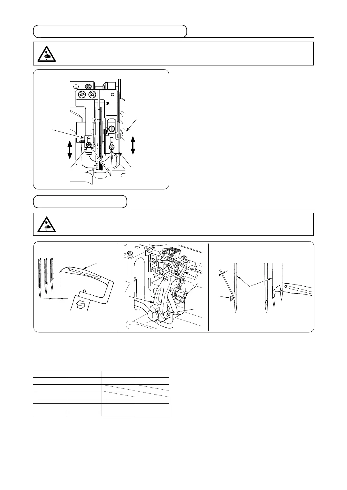
6. Adjusting the looper thread cam eyelet
WARNING :
To protect against possible personal injury due to abrupt start of the machine, be sure to start the follow-
ing work after turning the power off and ascertaining that the motor is at rest.
When the thread drawing amount is desired to be de-
creased in case of 2-needle machine or the like, loosen
screws
, move upward thread guides
and
and
tighten screws
to x them.
= Decrease
= Increase
Standard adjustment is achieved in the following state:
The lower end face of the thread guide is aligned with
the marker dot
The right and left thread guide thread paths are leveled
7. Adjusting the looper
WARNING :
To protect against possible personal injury due to abrupt start of the machine, be sure to start the follow-
ing work after turning the power off and ascertaining that the motor is at rest.
[Lateral position]
The relation between clearance A between looper
and
the center of right-hand needle and the needle gauge is as
shown in the table.
[Longitudinal position]
Adjust so that the clearance between blade point
of the
looper and medium needle
is 0 to 0.05 mm when the
top end of the looper comes from the extreme right posi-
tion to the center of the medium needle. After the adjust-
ment, tighten clamp screw
to x the looper.
* The blade point of the looper comes in contact with the
right-hand needle when rear needle guard
does not
work. So, be careful.
Loosen clamp screw
and laterally adjust looper holder
in accordance with the table.
Unit : mm
2-needle 3-needle
Needle gauge Return amount A Needle gauge Return amount A
3.2 4.9
4.0 4.5
4.8 4.1 4.8 4.1
5.6 3.7 5.6 3.7
6.4 3.3 6.4 3.3
0 - 0.05 mm
A
The right and
left thread guide
thread paths
are leveled
The lower end
face of the
thread guide
is aligned with
the marker dot
 Loading...