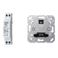
Image3: Connection diagram for 4-conductor circuit
(4) Automatic RMD
(5) Pulse insert with LB management motion detector cover or LB Management
push-button 1-gang
(6) Push-button, NO contact
CAUTION!
Overvoltage when connected to two phase conductors.
Destruction of the automatic RMD.
Connect to only a single phase.
Do not operate multiple automatic RMDs next to each other.
Avoid having heat sources, e.g. RMD dimmers, in the immediate vicinity of the auto-
matic RMD.
Ensure sufficient heat dissipation.
On control input A1 of the automatic RMD the aggregate current load must not
exceed 40 mA. To determine the current load, add together the current con-
sumption of all connected pulse inserts and lighting elements of the push-but-
tons.
If only pulse inserts with LB management motion detector cover or LB Management
push-button 1-gang are used, a maximum of 14 pulse inserts can be connected.
Power unit for rail mounting, Pulse insert
6 / 10
82599523 15.08.2022
J0082599523