Ensure that the wires cannot be pulled or pushed.
o Set the operating mode (see the Commissioning chapter). The set operating mode can be
changed at any time.
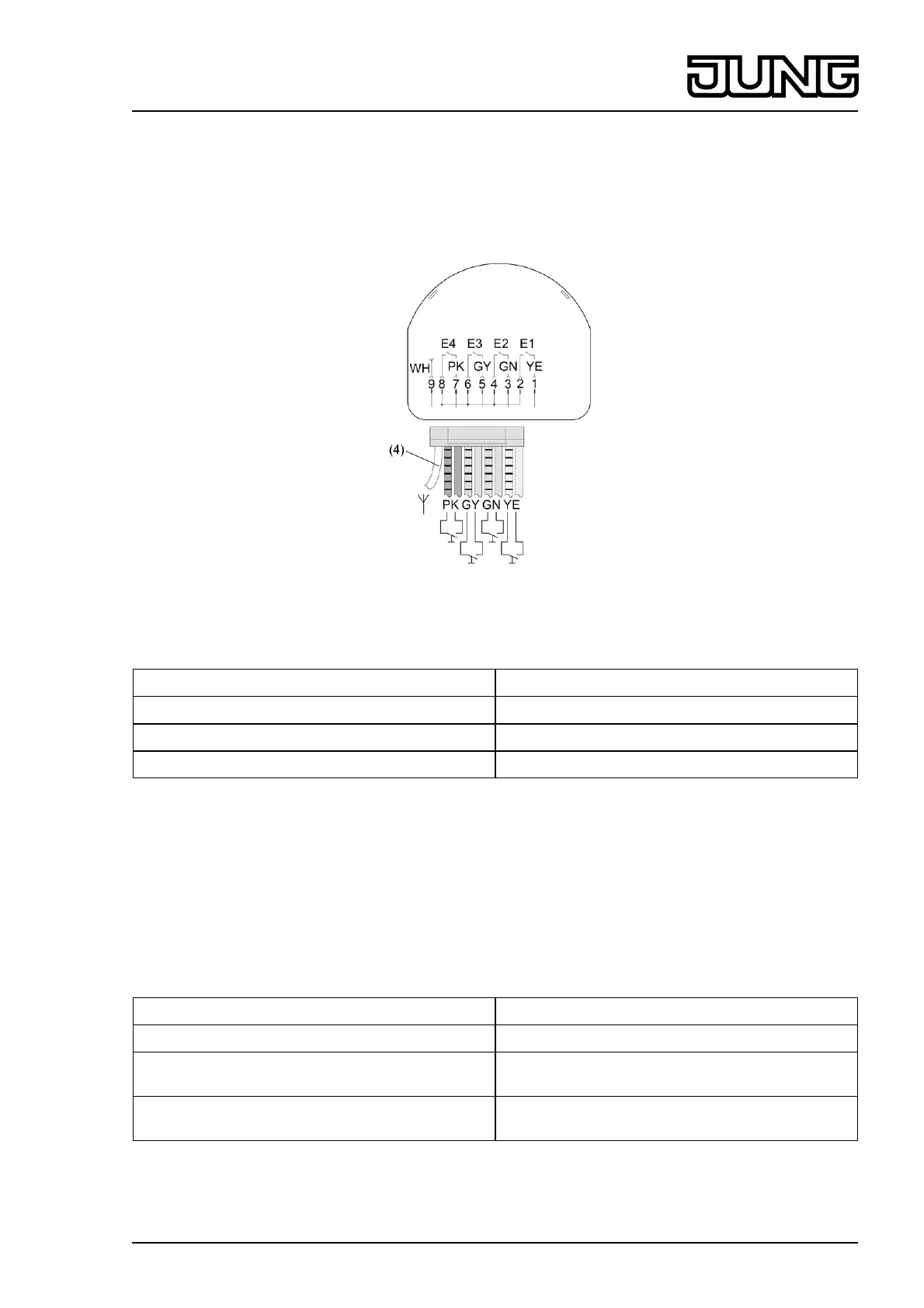
o Connect the connectors of the eight-wire cable (5) and the white antenna to the transmitter.
i Lay the antenna (4) stretched out freely if possible.
picture 6
Colour coding of the wires
Yellow (YE) and yellow/black Input E1
Green (GN) and green/black Input E2
Grey (GY) and grey/black Input E3
Pink (PK) and pink/black Input E4
The cables marked in black form a shared reference potential.
o Connect potential-free switches and buttons to the eight-wire cable.
o Insulate unused wires.
o Insert the transmitter (1) in the appliance box.
o Mount the switches and buttons (6) in the appliance box.
Replacing the battery
The battery is already inserted on delivery. Replacement is only necessary when the battery is
weak or empty.
LED display Meaning
LED flashes on transmission Battery OK
After transmission, LED again flashes very
quickly
Battery weak
LED does not flash on actuating a connected
button/switch
Battery empty
6/11
32535013
J:0082535013
13.08.2010
Radio Management
Radio multifunction transmitter