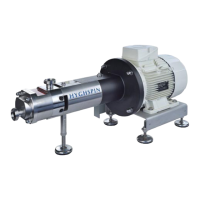
4 HYGHSPIN, release 01.2015
Screw in stud bolts (item 9) (do not insert completely)
Mount pump casing (item 2). When the main direction of rotation is rightward, the "VS"
stamped on the face must point down towards the cover (clockwise when looking towards
the end of the drive shaft)
Adjust flank clearance – see item 7. The flank clearances are pre-adjusted in our works
Mount pump casing (item 2)
Insert casing form ring (item 103) in cover
Mount cover (item 1)
Screw on and tighten cap nuts (item 100) with washers (item 101)
5 Removing the bearing support
Remove product-contact parts
Drain gear oil using the oil drain screw (item 19)
Unscrew cylindrical screws (item 122)
Remove gear cover (item 5) and flat gasket (item 128)
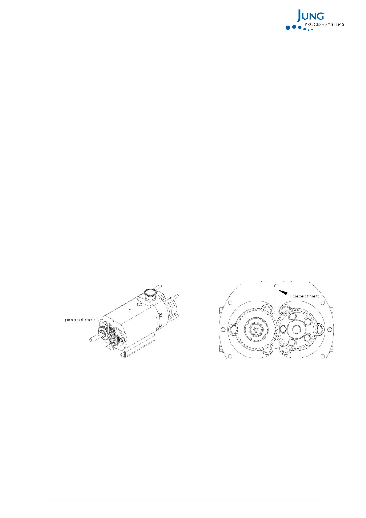
Block gearwheels (items 11 and 13) with the aid of a piece of soft metal aluminium )
Undo hexagonal screws (item 112) and remove together with washers (item 111)
Undo hexagonal screw (item 115)
Remove gearwheel (item 11) together with spring washer (item 12) and clamping sleeve
(item 10)
Undo hexagonal screw (Pos. 115)
Remove gearwheel (Pos. 13) with locking plate (Pos. 12) and coupling (Pos. 300)
Remove bearing covers (items 14 and 15) with Nilos ring (item 121)
Remove spacer sleeves (item 16)