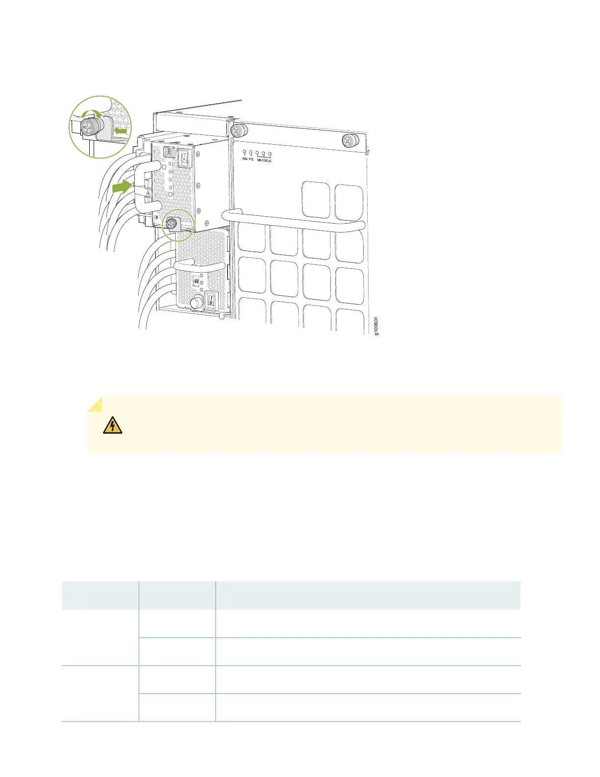
Figure 36: Installing a JNP10K-PWR-DC2 in PTX10008
17. Route INP1 cables to a power source and INP2 to another power source. The JNP10K-PWR-DC shares power, so if
power dips on one input, the power supply is able to load balance internally.
WARNING: Ensure that the power cords do not block access to router components or drape
where people can trip on them.
18. Set the three dip switches to set the inputs and whether the power supply is running at 3000 W, 5000 W, or 5500 W.
See Table 3 and Figure 37.
Set both enable switches to the on position when using both source inputs. When not using source redundancy, set
the unused source to the O (off) position. The LED turns red and indicates an error if a source input is not in use and
the enable switch is | (on).
Table 3: Setting the JNP10K-PWR-DC2 Dip Switches
FieldStateSwitch
IP0 is presentOn1
IP0 is not presentOff
IP1 is presentOn2
IP1 is not presentOff
40