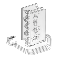
TA 211 E
10
English
Contents
1 Safety Notes ............................................................. 10
2 Application
................................................................. 10
3 Technical Data
........................................................ 10
4 Mounting
..................................................................... 11
5 Electrical Connection
.......................................... 11
6 Placing into Operation
........................................ 12
7 Operation of the Regulator
.............................. 12
8 Programming the time switch
........................ 15
9 General Notes
......................................................... 15
10 Malfunction
................................................................ 15
1 Safety Notes
The regulator is installed into the boiler
facia. The regulator may only be con-
nected according to the wiring diagram.
Under no circumstances should the reg-
ulator be connected to the 230 V mains.
The regulator is to be used exclusively
in connection with a boiler equipped with
Bosch Heatronic control.
Before installing the regulator, the volt-
age supply (230 V, 50 Hz) to the boiler
must be disconnected.
2 Application
TA 211 E is a flow temperature regulator con-
trolled by outside temperature to be installed
into the facia of appliances, equipped with
Bosch Heatronic control.
2.1 Items Supplied
Included in the items supplied (Fig. ) with
the TA 211 E is an outside temperature sen-
sor with mounting material.
2.2 Accessories
A mechanical flow temperature limiter must
be fitted to the flow pipe of underfloor heating
systems, in accordance with the manufactur-
er's instructions.
The TA 211 E is supplied without a time
switch. This is available as an accessory.
A remote control with a time switch can also
be used (not in UK, see the following table)
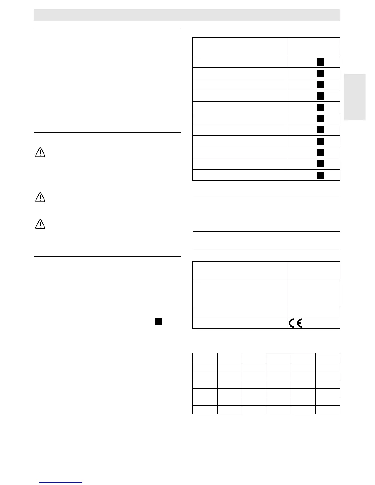
The following combinations are permisable:
* Not in UK.
Note: According to Par. 7 of the Heating
System Regulations, the TA 211 E
can be operated only in conjunction
with a time switch.
3 Technical Data
3.1 Measured Values,
Outside Temperature Sensor AF
2
Combination Electrical Cir-
cuit Diagram
TA 211 E + EU 3 T
Fig.
TA 211 E + DT 1
Fig.
TA 211 E + EU 2 D
Fig.
TA 211 E + DT 2
Fig.
TA 211 E + EU 3 T + TW 2
Fig.
TA 211 E + DT 1 + TW 2
Fig.
TA 211 E + EU 2 D + TW 2
Fig.
TA 211 E + DT 2 + TW 2
Fig.
TA 211 E + TFQ 2 T
Fig.
TA 211 E + TFQ 2 W
Fig.
TA 211 E + TFP 3
Fig.
Measuring range of the
outside temperature sensor – 20 …+30 °C
Permissible ambient
temperature of the outside
temperature sensor – 30 … +50 °C
Protection class III
°C Ω
AF
V°CΩ
AF
V
– 20 2392 2.64 4 984 1.65
– 16 2088 2.49 8 842 1.49
– 12 1811 2.33 12 720 1.34
– 8 1562 2.16 16 616 1.20
– 4 1342 1.99 20 528 1.07
0 1149 1.82 24 454 0.95
8
8
8
8
9
9
9
9
10
10
10
 Loading...