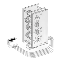
TA 211 E
12
English
With the installation of the TA 211 E Regu-
lator, the electronics of the heating unit au-
tomatically use the pump switching type III
(continuous pump operation), also when
the factory setting was not changed!
The figures and are schematics of the
application of the TA 211 E with radiator and
floor heating systems.
The corresponding electrical connection dia-
gram (Figure to ) is to be used.
Legend for the Figures to
:
P
I
Circulation pump
SF Storage temperature sensor (NTC)
B
2
Mechanical flow temperature limiter
(only in connection with underfloor
heating systems)
AF Outside temperature sensor
WS Warm water storage
RK Check valve
E Venting valve
5.1 Electrical Connection of the Outside
Temperature Sensor (AF)
• Remove the cover (AF
c
with AF
b
, Fig. ).
• Insert the cable through the threaded
fitting (AF
d
) and connect to the two termi-
nals (AF
e
).
• Tighten the threaded fitting (AF
d
) so that
strain relief and splash water protection is
provided at the cable feed-through.
• Close the outside sensor.
• On the boiler, insert the cable through the
protective sleeve and secure with the strain
relief.
• Connect the cable to the TA 211 E on the
terminals “A” and “F” (Figure to ).
5.2 Electrical Connection of Accessories
(Figure to )
5.2.1 Time Switch
• Connect the time switch (if available) ac-
cording to Figure on the main circuit
board of the boiler to connector ST 5 .
5.2.2 Remote Control (not in UK)
• Connect the TW 2 Remote Control
(in case available) on the TA 211 E to the
terminals 3 and 4 (Fig. ).
• Connect the TFQ 2 T, TFQ 2 W or TFP 3
Remote Controls (in case available) to the
terminals 1, 3 and 4 (Fig. ).
5.2.3 Mechanical Flow Temperature
Limiter
• An additional mechanical flow temperature
limiter is to be connected to the feed of floor
heating systems. The electrical connection
is to be made according to the installation
instructions of the heating unit.
5.3 Closing the Switching Box
• Replace the cover (h) and screw in the
screw (g, Fig. ).
• Snap in the cover (f, Fig. ).
6 Placing into Operation
By operating the boiler, the TA 211 E Regula-
tor is also activated.
7 Operation of the Regulator
Legend for the Figures and :
a
I
Outside temperature for boiler switch-
ing off point
b Operating Mode Switch
c Base point
d Night Reduction
e Maximum flow temperature
VT Flow temperature
AT Outside temperature
MVT Average feed temperature
6 7
8 10
6 10
3
8 10
8 10
8
9
 Loading...