INSTALLATION
,
USE AND MAINTENANCE MANUAL
–
LC 300-420-580
REV
Via Crosera n° 50
33082 Azzano Decimo, PN (Italia)
http://www.jurop.it
e-mail: info@jurop.it
6.1. Ordinary maintenance
• Installation and maintenance must be operated only by qualified personnel wearing the proper clothes and the necessary tools as well as
protection devices.
• Use suitable protection equipment (gloves, protection glasses, boots...)
• In the following table summarizes the main controls to be performed and the frequency of intervention.
Operating condition Maintenance Area Check 8
H
50
H
500
H
1500H
OPERATING
Transmission Rotation speed
Pump
Lubrication: dripping into oilers
Operating pressure
Sound pressure level
STANDSTILL
Pump
Drain the oil gathered in the exhaust separator
Check vanes wear
Clean filter and vacuum line shutoff
Check pressure relief valve condition
Side mounted tank oil level
Gear box oil level
Gear box oil change (*)
Cooling system venting
Pump’s inner washing (**)
(*) The first oil change must be done inside 500 hours operation. Following
changes every 5000 hours or 12 months. In order to choose the most suitable oil, see
paragraph 2.5.
(**) After operation in dusty environments, after accidental sucking of liquids
inside the pump or before a long inoperativity period it is recommended to wash the
pump inside according to the procedure described at paragraph 5.2.
Checking the drip oilers
• Check dripping into the oilers.
• Be sure it is regular (about 40 drops/min at max. speed, with
degree of vacuum > 50%) to grant a correct lubrication of the pump. At
lower speeds, the number of drops must be directly proportional.
If the pump is run without lubrication, the internal
components may quickly damaged due to
overheating. Stop the vacuum pump and check
the oil level and the lubricating pump.
Checking the side mounted oil tank level
• Do not run the pump with oil level under the minimum level: that
may lead to dry functioning and cause serious damages.
• Tank capacity: 4l.
• Use pure fresh oil.
Do not re-use the exhausted oil gathered on the
bottom of the exhaust silencer.
Checking the vanes wear LC300 - LC420
• Unscrew the vanes wear check-plug on the housing (pos. CL).
• Turn the shaft until you see the vane.
• The vanes should slide to the bottom of the seat due to gravity:
check they really do.
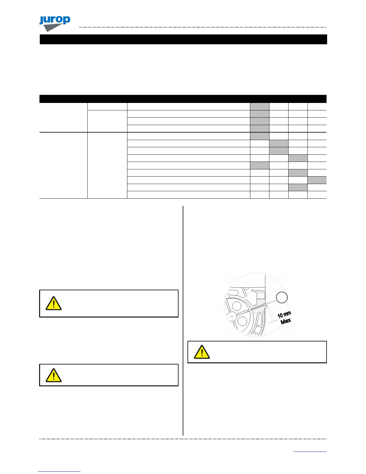
• Insert a rod of 6 mm Ø with its conic end towards the pump (rod
supplied with pump).
• Turn the shift manually and touch the outside diameter of the rotor
with the checking rod, mark it a first time. Keep turning the shift till the
rod falls inside a vane groove. Mark it again and measure the gap
between the two marks.
• If this gap exceeds 10 mm, then the vanes must be replaced.
• At the end of this procedure, do not forget to replace the plug.
• Replace all vanes at the same time.
Pic. 6.1
Replace the vanes when their wear exceeds 10
m\m (L – L min): they may break. Replace all
vanes at the same time.
Checking the vanes wear LC580
• Unscrew the vanes wear check-plug on the front flange (pos. CL).
• Turn the shaft until you see the vane.
• The vanes should slide to the bottom of the seat due to gravity:
check they really do.
• Replace the vanes when their wear exceeds 10 m\m (L – L min):
they may break.
• At the end of this procedure, do not forget to replace the plug.
• Replace all vanes at the same time.
 Loading...