11
What is the MASTER Output for ?
It is used to operate the pump of an electro-hydraulic power pack or maybe a clutch pump. It can
also be used for powering a dump valve, master valve etc. It can be congured to work
continuously, that is ON when START is pressed and OFF when STOP is pressed; or in parallel with
any output (default setting), that is, it is active only a function is operated. If it is needed with
certain functions only, this can easily be congured.
Contents
CONTENTS
CONTENTS
Guarantee, service, repairs and maintenance
Chapter1: Customer infomation
General Information on Safety
Chapter2: General description
General description
END USER INSTRUCTIONS
Chapter 3:
Receiver
Wiring Diagram
Chapter 4: Troubleshooting
Guarantee, service, repairs and maintenance
The JUUKO products are covered by a guarantee/warranty against material,
construction and manufacturing faults. During the guarantee/warranty period, JUUKO
may replace the product or faulty parts. Work under guarantee/warranty must be
carried out by JUUKO or by an authorized service centre specied by JUUKO.
This is not covered by the guarantee/ warranty:
▪Faults resulting from normal wear and tear
▪Parts of a consumable nature
▪Products that have been subject to unauthorized modications
▪Faults resulting from incorrect installation and use
▪Condensation and water damage
Maintenance:
▪Repairs and maintenance must be carried out by qualied personnel
▪Use spare parts from JUUKO only
▪Contact your representative if you require service or other assistance
▪Keep the product in a dry, clean place
▪Keep contacts and antennas clean
▪Wipe o dust using a slightly damp,clean cloth
1. The Receiver is designed to carry a maximum of 15 Amps. That is, for example,15 Amps through
one output or 5 Amps each through 3 outputs.
2. Master Output. This can be congured to Continuous or Parallel operation, see wiring diagram
for details.
3.Safety Feature. Both the Transmitter and the Receiver will “time out” after 30 minutes of
inactivity. This can be altered, ask your dealer.
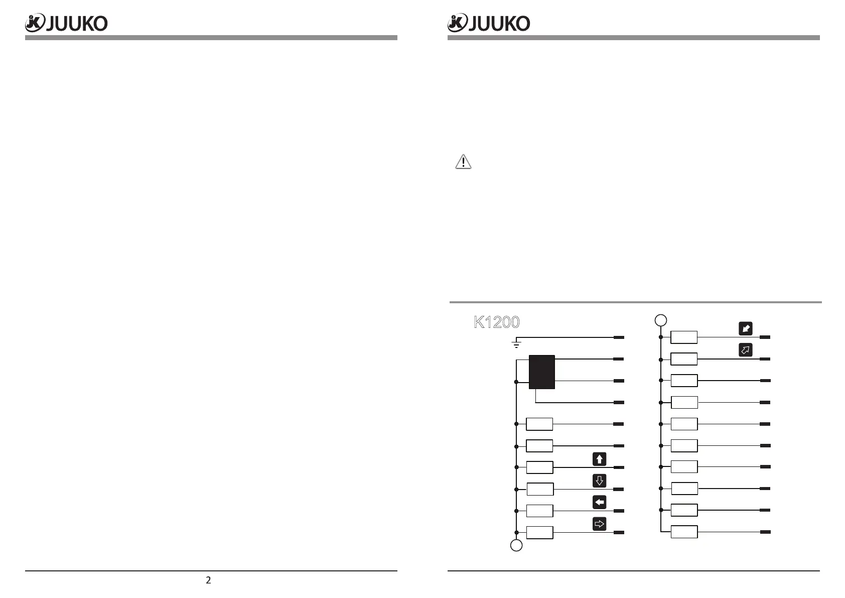
Chapter 3: Receiver
2
3
4
7
12
K1200
A
DC-
DC+
DC+
E.STOP
UP
DOWN
EAST
WEST
SOUTH
NORTH
1
2
3
4
5
6
HORN
N/A
Master output
1
2
3
4
5
6
7
8
9
10
11
12
13
14
15
16
17
18
19
20
Power enable (DC-)
Y1
Y2
Y3
Y4
Y5
Y6
Y7
Y8
Y9
Y10
Y11
Y12
Y13
Y14
Y15
A