8
Technical data
Dimensions
Typical response time for Stop
command and commands
Typical operating range
Modulation method
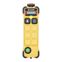
Control system
Antenna impedance
Power supply
Antenna
Average power consumption
Radio-frequency power
Weight (including battery)
Housing material
Protection degree
Operating and storage temperature
193×57×51mm
50mS~100mS
100M
4 FSK
PLL
50Ω
LR6(AA)1.5V x2
16mA@DC3V (default setting)
<10dBm (default setting)
approx.325g
PA6(30% GF)
IP65
(-20°C)~(+55°C) / (-40°C)~(+65°C)
Frequency range
434.040Mhz~434.790Mhz
TRANSMITTER
Internal
Changing the batteries:
BATTERY TYPE:
AA (HR6) Ni - MH x 2
The zero-g safety function can prevent the uncontrolled output of commands in
specic emergencies. The G sensor can detect if the transmitter receives a hard
impact, dropped or thrown. These features can deactivate either the complete
radio system or only the safety-relevant function relays. Alternatively, a pre-dened
output (e.g. crane horn) can be triggered. Please contact your dealer for special settings.
Zero-G safety
Chapter 2: General description
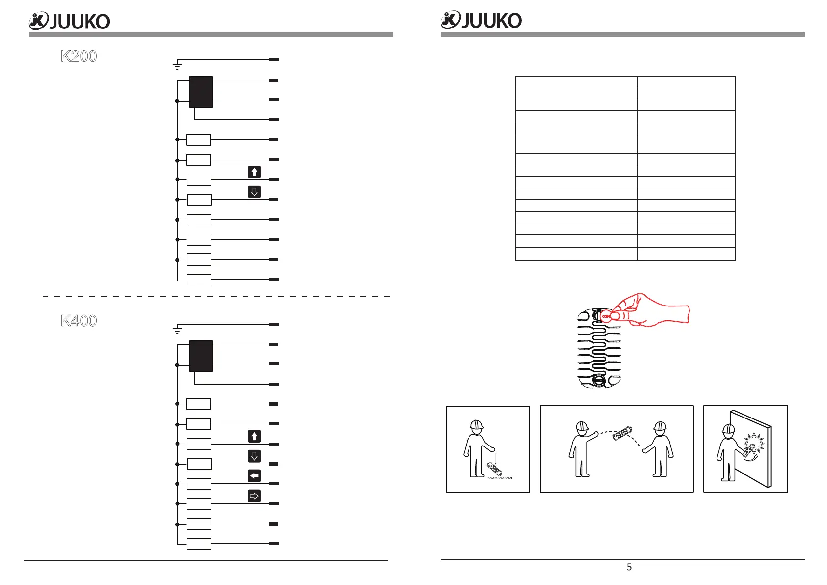
Chapter 3: Wiring Diagram
K200
K400
4
5
6
7
8
9
10
11
Black
Brown
RED
Orange
Yellow
Green
Blue
Purple
Gray
White
Pink
Lime
DC-
DC+
DC+
E.STOP
UP
DOWN
HORN
NA
NA
NA
Master Output
Power enable (DC-)
Y1
Y2
Y3
Y4
Y5
Master Output
4
5
6
7
8
9
10
11
Black
Brown
RED
Orange
Yellow
Green
Blue
Purple
Gray
White
Pink
Lime
DC-
DC+
DC+
E.STOP
UP
DOWN
EAST
WEST
HORN
NA
Power enable (DC-)
Y1
Y2
Y3
Y4
Y5
Y6
Y7