Do you have a question about the JVC A-X55 and is the answer not in the manual?
Details output power, total harmonic, and intermodulation distortion.
Covers frequency characteristics and damping factor specifications.
Lists input terminal specs and signal-to-noise ratios.
Describes tone controls, filters, and loudness features.
Outlines general specs, power source, dimensions, and weight.
Describes the fundamental setup of the Dynamic Super A amplifier.
Explains the operational principles of the Dynamic Super A circuit.
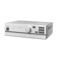
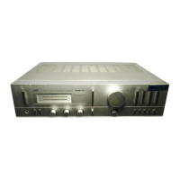
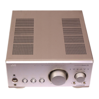
Identifies components located on the front panel.
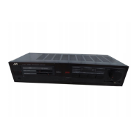
Identifies components located on the rear panel.
Identifies components located on the top panel.
Details the procedure for adjusting drive amplifier center voltage.
Details the procedure for adjusting power amp idling current.
Lists components for the TXX-376 Equalizer Amplifier PC Board.
Lists components for the TXX-373 Drive Amplifier PC Board.
Lists components for the TXX-374 Power Amplifier PC Board.
Lists components for TPS-287C, TPS-287D, TPS-287E AC Unit PC Boards.
| Type | Integrated Amplifier |
|---|---|
| Power Output | 55W per channel into 8Ω |
| Frequency Response | 10Hz-50kHz |
| Total Harmonic Distortion | 0.02% |
| Signal-to-Noise Ratio | 100dB |
| Signal to noise ratio | 100dB |
| Dimensions | 435 x 120 x 350mm |
| Weight | 8.7kg |
| Input sensitivity | 2.5mV (Phono), 150mV (Line) |
| Inputs | Phono, Tuner, Aux, Tape |
| Outputs | Tape |
| Speaker load impedance | 4Ω to 16Ω |